21-i-001
Disclaimer and Conditions Regarding Use of SWGDE Documents:
SWGDE documents are developed by a consensus process that involves the best efforts of relevant subject matter experts, organizations, and input from other stakeholders to publish suggested best practices, practical guidance, technical positions, and educational information in the discipline of digital and multimedia forensics and related fields. No warranty or other representation as to SWGDE work product is made or intended.
As a condition to the use of this document (and the information contained herein) in any judicial, administrative, legislative, or other adjudicatory proceeding in the United States or elsewhere, the SWGDE requests notification by e-mail before or contemporaneous to the introduction of this document, or any portion thereof, as a marked exhibit offered for or moved into evidence in such proceeding. The notification should include: 1) The formal name of the proceeding, including docket number or similar identifier; 2) the name and location of the body conducting the hearing or proceeding; and 3) the name, mailing address (if available) and contact information of the party offering or moving the document into evidence. Subsequent to the use of this document in the proceeding please notify SWGDE as to the outcome of the matter. Notifications should be sent to secretary@swgde.org.
From time to time, SWGDE documents may be revised, updated, or sunsetted. Readers are advised to verify on the SWGDE website (www.swgde.org) they are utilizing the current version of this document. Prior versions of SWGDE documents are archived and available on the SWGDE website.
Redistribution Policy:
SWGDE grants permission for redistribution and use of all publicly posted documents created by SWGDE, provided that the following conditions are met:
- Redistribution of documents or parts of documents must retain this SWGDE cover page containing the Disclaimer and Conditions of Use.
- Neither the name of SWGDE nor the names of contributors may be used to endorse or promote products derived from its documents.
- Any reference or quote from a SWGDE document must include the version number (or creation date) of the document and also indicate if the document is in a draft status.
Requests for Modification:
SWGDE encourages stakeholder participation in the preparation of documents. Suggestions for modifications are welcome and must be forwarded to the Secretary in writing at secretary@swgde.org. The following information is required as a part of any suggested modification:
- Submitter’s name
- Affiliation (agency/organization)
- Address
- Telephone number and email address
- SWGDE Document title and version number
- Change from (note document section number)
- Change to (provide suggested text where appropriate; comments not including suggested text will not be considered)
- Basis for suggested modification
Intellectual Property:
Unauthorized use of the SWGDE logo or documents without written permission from SWGDE is a violation of our intellectual property rights.
Individuals may not misstate and/or over represent duties and responsibilities of SWGDE work. This includes claiming oneself as a contributing member without actively participating in SWGDE meetings; claiming oneself as an officer of SWGDE without serving as such; claiming sole authorship of a document; use the SWGDE logo on any material and/or curriculum vitae.
Any mention of specific products within SWGDE documents is for informational purposes only; it does not imply a recommendation or endorsement by SWGDE.
1. Purpose
The purpose of this document is to provide image analysis practitioners information as to the historical background of Reverse Projection Photogrammetry (RPP), as well as the technical foundation, methodology, and limitations when engaging in Forensic Image Analysis.
2. Introduction
RPP is a form of photogrammetry involving the projection of an image from a camera onto a new image from the same camera or a camera with similar parameters, to include focal length, distortion, position and orientation.1 This document addresses technical issues specific to Reverse Projection Photogrammetry.
3. Historical Background
Multiple methods exist for completing photogrammetric examinations, including direct scaling, reverse projection photogrammetry, analytical photogrammetry, and laser scanning photogrammetry. Each of these methods have been shown (depending on multiple factors inherent to the imagery) to allow a trained examiner to make precise and accurate measurements to answer case-related questions.
Photogrammetry traces its roots to Leonardo Da Vinci’s seminal work in perspective,2 published during the 15th century. With the advent of photography in the 1850s, photogrammetry took on new usages, and the term “photogrammetry” was coined in 1867. The relationship between projective geometry and photogrammetry was first developed by Sturms and Hauck in Germany in 1883.3
Records of photogrammetry in forensic science can be traced to cases within the 1960s. As an example, Everett Merritt took part as a photogrammetric consultant in the Photography Evaluation Panel during the Warren Commission, which published their report in 1964.
RPP was a product of more surveillance being used in banks following the enactment of the Federal Bank Surveillance Act of 1967. Although other forms of forensic image analysis were not always viable, including face comparison, determining the height of the subject became a primary investigative technique.
Initial RPP exams used 35mm film cameras that had been modified to utilize the surveillance cameras’ individual frames of film to overlay the captured incident with a live view of the location. As surveillance progressed to CCTV and analog video was the new medium, analog video mixing boards were used for the overlay process. Since digital video has become the standard, software-based solutions are now used for the overlay and capture of the frames needed for the RPP examination.4
4. Expertise Training
Before conducting forensic RPP, individuals should have expertise in imaging science, knowledge of analog and digital video, and have an understanding of photogrammetric methodology. Image science expertise is necessary to understand perspective, image resolution, image distortion and aspect ratio in the image creation process. Understanding of human motion is necessary for the purposes of image selection and the interpretation of results. This combination of expertise may require both formal training and practical experience (i.e., on-the- job) among multiple disciplines, or it may require the involvement of multiple individuals with a variety of expertise.
For more information, see SWGDE Training Guidelines for Video Analysis, Image Analysis and Photography.
5. Technical Foundations
There are a number of critical factors that form a technical foundation for forensic RPP. The physics and geometry of the photographic process provide the capabilities for conducting this type of photogrammetric examination.
A camera placed in a particular position and location captures the unique projective geometry from the reflected light of the objects in the scene. The physics of this imaging process create a unique two-dimensional reproduction of the scene.5 Therefore, if the same or a different camera is placed in the same position and location, the geometry of that scene can be accurately reproduced. This is why it is possible to take accurate measurements from an image using a known measuring device in the scene after the original capture.
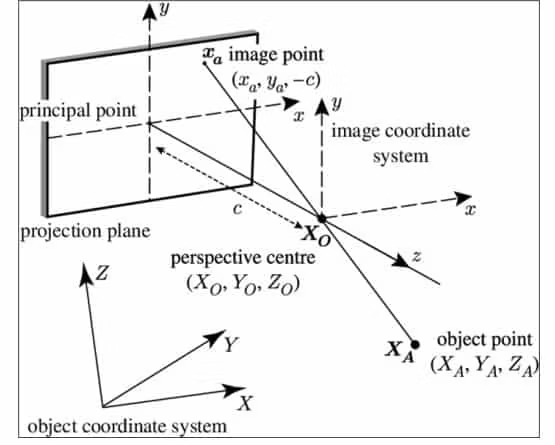
Figure 1. Central perspective projection. XA is an object point in threedimensional space, which is projected through the perspective centre XO onto the projection plane where it creates the image point xa. The distance between the principal point and the perspective centre, orthogonal to the projection plane, is the principal distance, c. {X,Y,Z} is the object coordinate system, located arbitrarily in space. The perspective centre XO and the point XA have the coordinates (XO,YO,ZO) and (XA,YA,ZA), respectively. The image coordinate system, {x,y,z}, has its origin at XO and the z -axis coincides with the principal point and the perspective centre. The x – and y-axes are parallel to the projection plane and the image point xa has the coordinates (xa,ya,Kc) (redrawn from Atkinson (1996)) Published in Journal of The Royal Society Interface 20086
Focal length and lens distortion are factors that have to be reproduced when conducting a RPP examination.
The use of different focal lengths to capture different images of the same scene does not, in theory, change the projective geometry present in the scene. But two different focal lengths will produce different size scales of the scene. If the lens distortion within the recorded and live views is not the same, then stationary objects affected by the distortion will not align. These factors will make confirmation of the registration of the live and recorded scene impossible. Therefore, focal length and lens distortion need to be the same when conducting the RPP examinations.
A calibrated measuring device that is of sufficient size should be used when determining the needed distance, length, height or width of the questioned object. The size of the measuring device is sufficient if it is both large enough to measure the object of interest and also large enough to provide discrete visible measurements based on the spatial resolution of where the object is in the scene.
6. Methodology
6.1 Evaluate the submission
Determine if the submitted material is suitable for analysis. The laboratory should determine appropriate requirements for the minimum resolution needed for a viable reverse projection photogrammetric examination. For example, if the resolution of the measured individual is less than one pixel per six inches, the viability of the examination should be reconsidered.
Suitability requires that the object must be entirely visible and is large enough based on the practitioner’s experience and training. Further, the practitioner must examine the image for the presence of potentially stationary objects in the foreground and background so the camera station can be confirmed or replicated. Likewise, an assessment should be conducted as to whether the angle of capture of the original scene is too great. An example of a too great angle would be a surveillance camera directly over the object.
6.2 Preparing imagery for analysis
Produce working copies of the imagery to be subjected to analysis. This may require digitization from negatives, prints, or conversion from other media. Enhance images for the examination. This can include basic contrast, lightening and darkening of the image to make the scene objects more visible for the RPP examination. If multiple images are suitable for analysis, a subset should be prepared, saved, and printed for the onsite examination.
6.3 Verifying the scene integrity
The scene must have retained the stationary foreground and background objects that were observed in the evaluation phase of the examination. The camera which captured the incident scene is not required but preferred to be present, operational and in its original location. The original camera is preferred because the image properties (lens distortion, resolution, and focal length) should be consistent with the original captured image. Depending on the agency’s resources this could be a verbal confirmation from the investigator or owner of the location, but the practitioner will ultimately verify the scene integrity onsite.
6.4 Onsite evaluation
Once onsite, the camera station should be checked for location, access, and connectivity. Based on the original capture as depicted in the printed image, confirm that the camera station is in a similar location. The practitioner should ensure there is a live feed from the camera of interest, which can be through a direct connection to the back of the camera or through a connection at the recorder.7
6.5 Onsite examination
Connect the live view to the mixing software. Through the mixing software verify the alignment between the captured scene and the live view to ensure the images are aligned. There may be size issues between the captured scene and the live view, to include aspect ratio and/or resolution differences. Positional adjustment of the camera may also be necessary but should not include changing the focal length. Changing the focal length should be considered only after the camera position has been confirmed and determined to be necessary in order to match the captured scene.
Once alignment between the captured scene and the live view has been achieved, utilize a known object or person by placing them in the location of the questioned item in the scene to ensure accurate placement of the measuring device. In determining the height of an individual, this generally involves placing a person in position to determine the center of gravity of the person to be measured, and then following with a calibrated height chart placed at the center of gravity. The measuring device should be calibrated and placed in the scene to traverse the object of interest.8 Evaluation of the placement should be done through the recording software to ensure the measurement markers are visible. Conditions may be impacted by lighting conditions on scene. Once the measuring device has been placed and recorded, the recording should be verified and then measurements should be made. Measurements from the center of the lens of the camera to the ground and the distance on the ground between the camera and the measuring device should be recorded. These measurements can be used to derive the degree of uncertainty associated with this examination.9
7. Reporting Conclusions
Based on the observations and measurements, a conclusion may be reached. This may or may not involve a numerical result. For example, placing an object back into a scene based on the surveillance image would not entail a numerical result, as a visual result is an appropriate conclusion.
The basis for, and uncertainty of, any conclusions should be documented and reported. Possible contributions to uncertainty may come from measurable (e.g., resolution and positional accuracy) and non-measurable (e.g., gait, posture, shoe wear, etc.) factors. Equations, such as those for image resolution10 and positional accuracy11 of the measuring device, can be used to address some of these uncertainties. In subject height analysis, the measurement is captured at only a single moment of time. Given that multiple factors can change a subject’s stature, such as choice of footwear, choice of headwear, positioning in gait, and the natural circadian rhythms of the human body, the measured height can be no more than an estimate.
The estimated height, as well as calculated uncertainty, can be used to determine whether a suspect can be excluded or included, as height is a class characteristic.
The image resolution of the object of interest at the given plane (not the spatial resolution) determines the precision of the measurement that can be quantified. For instance, if one pixel is equal to ¼” in the object plane of the image, then the smallest measurement possible would be to a ¼”.
The results of the examination should undergo independent review by a comparably trained individual. If disputes during review arise, a means for resolution of issues should be in place.
For additional information, see SWGDE Best Practices for the Forensic Use of Photogrammetry, Appendix A: Reporting Conclusions through Quantitative Means.
History
| Revision | Issue Date | Section | History |
|---|---|---|---|
|
1.0 DRAFT |
2021-01-14 |
Imaging |
Initial draft created and voted by SWGDE for release as a Draft for Public Comment. |
|
1.0
DRAFT |
2021-06-17 |
Imaging |
Draft for public comment re-released for Public Comment. |
|
1.0 |
2022-01-13 |
Imaging |
Document voted for release as final publication |
1 Photogrammetry in Digital Forensics, in Handbook of Digital Forensics of Multimedia Data and Devices, First Edition. Edited by Anthony T.S. Ho and Shujun Li. John Wiley & Sons, Ltd, pg. 192-193, 2015.
2 Of Linear Perspective, in Leonardo da Vinci’s note-books, Arranged and rendered into English with introductions by Edward McCurdy, M.A., pg. 213-214, 1906.
3Hauck, G., Konslruklion einer Dritten Perspeklive einer Objekles aus Zwei Gegebenen Perspekliven, 1883.
4 David J. Massa, Sigma Animation, Inc., Using Computer Reverse Projection Photogrammetry to Analyze an Animation, International Congress and Exposition, Detroit, Michigan, March 1-4, 1999.
5 Measurement Good Practice Guide No. 80, in Fundamental Good Practice in Dimensional Metrology, David Flack & John Hannaford, Chapter 9, pg. 156-157, 2005.
6 Simon M. Walker, Adrian L. R. Thomas, Graham K. Taylor, Photogrammetric reconstruction of high-resolution surface topographies and deformable wing kinematics of tethered locusts and free-flying hoverflies, Journal of The Royal Society Interface 6, pg. 351–366, 2009.
7 Edward M. Robinson, Crime Scene Photography, pg. 455-462, 2007.
8 Forensic Photogrammetry, in Forensic Second Edition Engineering, by William G. Hyzer, pg 346-379, 2001.
9Meline, K.A. & Bruehs, W. E., A Comparison of Reverse Projection and Laser Scanning Photogrammetry, Journal of Forensic Identification, 68(2), pg. 281-292, 2018.
10 Image resolution = Object in inches / image in pixels, where the object is a known measurement (for example, a height chart).
11 PA = (Hc – Ho)/Dh
Hc = height of the camera (in inches)
Ho = height of the object (reported measurement taken from reverse projection; in inches) Dh = horizontal distance from the camera to the subject (in inches)
Dh = horizontal distance from the camera to the subject (in inches)
Result should be multiplied by +/-3 inches
Version: 1.0 (January 13, 2022)