19-v-001
Disclaimer and Conditions Regarding Use of SWGDE Documents:
As a condition to the use of this document and the information contained therein, the SWGDE requests notification by e-mail before or contemporaneous to the introduction of this document, or any portion thereof, as a marked exhibit offered for or moved into evidence in any judicial, administrative, legislative or adjudicatory hearing or other proceeding (including discovery proceedings) in the United States or any Foreign country. Such notification shall include: 1) the formal name of the proceeding, including docket number or similar identifier; 2) the name and location of the body conducting the hearing or proceeding; 3) subsequent to the use of this document in a formal proceeding please notify SWGDE as to its use and outcome; 4) the name, mailing address (if available) and contact information of the party offering or moving the document into evidence. Notifications should be sent to secretary@swgde.org.
It is the reader’s responsibility to ensure they have the most current version of this document. It is recommended that previous versions be archived.
Redistribution Policy:
SWGDE grants permission for redistribution and use of all publicly posted documents created by SWGDE, provided that the following conditions are met:
- Redistribution of documents or parts of documents must retain the SWGDE cover page containing the disclaimer.
- Neither the name of SWGDE nor the names of contributors may be used to endorse or promote products derived from its documents.
- Any reference or quote from a SWGDE document must include the version number (or create date) of the document and mention if the document is in a draft status.
Requests for Modification:
SWGDE encourages stakeholder participation in the preparation of documents. Suggestions for modifications are welcome and must be forwarded to the Secretary in writing at secretary@swgde.org. The following information is required as a part of the response:
- Submitter’s name
- Affiliation (agency/organization)
- Address
- Telephone number and email address
- Document title and version number
- Change from (note document section number)
- Change to (provide suggested text where appropriate; comments not including suggested text will not be considered)
- Basis for change
Intellectual Property:
Unauthorized use of the SWGDE logo or documents without written permission from SWGDE is a violation of our intellectual property rights.
Individuals may not misstate or over represent duties and responsibilities of SWGDE work. This includes claiming oneself as a contributing member without actively participating in SWGDE meetings; claiming oneself as an officer of SWGDE without serving as such; claiming sole authorship of a document; use the SWGDE logo on any material or curriculum vitae.
Any mention of specific products within SWGDE documents is for informational purposes only; it does not imply a recommendation or endorsement by SWGDE.
1. Purpose
The purpose of this document is to explain the storage and transmission of H.264 coded video for forensic practitioners. An understanding of the H.264 standard, as well as two common implementations will help to provide the practitioner with the ability to understand and organize packet and frame information, as well as validate tools that utilize the format information at the byte level. This information can also aid in decoding video data from H.264 coded video streams as well as unstructured or buffered data sets where a stream has not been defined, or a file has become damaged.
2. Scope
This document will discuss how coded video is stored as binary streams within standard implementations of H.264. The specifics discussed are H.264’s AVCC and Annex B implementations for storing components of frame data and format information. A bit and byte level discussion for manually decoding these components will be discussed.
3. Limitations
This is not intended to replace or transcribe the H.264 ITU-T/ISO standard (1). Information specifically relevant to the storage of H.264 coded video will be included in this document. This document is not intended to be an instruction document on how to manually parse video data, but is to be used to better understand how this process could be accomplished. This document does not discuss H.264 when accompanied by an audio stream, as there could be several audio codecs integrated within a video file. This document does not address how video information is read or how to interpret data in binary and hexadecimal viewers.
This document does not discuss picture decoding or compression. (For more information about compression at a high level can be found in SWGDE Fundamental of Digital File Formats.)
4. Terminology
- Access unit: A set of the Network Abstraction Layer (NAL) units always containing a primary coded picture. In addition to the primary coded picture, an access unit may also contain one or more redundant coded pictures or other NAL units not containing slices or slice data partitions of a coded picture. The decoding of an access unit always results in a decoded picture.
- Byte stream: An encapsulation of a NAL unit stream containing start code prefixes and NAL units as specified in Annex B.
- Coded picture: A coded representation of a picture. A coded picture may be either a coded field or a coded frame. Coded picture is a collective term referring to a primary coded picture or a redundant coded picture, but not both together.
- Coded video sequence: : A sequence of access units that consists, in decoding order, of an instantaneous decoding refresh (IDR) access unit followed by zero or more non-IDR access units including all subsequent access units up to but not including any subsequent IDR access unit.
- IDR access unit: An access unit in which the primary coded picture is an IDR picture.
- IDR picture: A coded picture containing only slices with I or SI slice types that causes a “reset” in the decoding process. After the decoding of an IDR picture, all following coded pictures in decoding order can be decoded without inter prediction from any picture decoded prior to the IDR picture.
- Network abstraction layer (NAL) unit: Syntax structure containing an indication of the type of data to follow and bytes containing that data in the form of a raw byte sequence payload (RBSP) interspersed as necessary with emulation prevention bytes.
- Primary coded picture: The coded representation of a picture to be used by the decoding process for a bitstream conforming to H.264. The primary coded picture contains all macroblocks of the picture.
- Redundant coded picture: A coded representation of a picture or a part of a picture. The content of a redundant coded picture shall not be used by the decoding process for a bitstream conforming to H.264. The content of a redundant coded picture may be used by the decoding process for a bitstream that contains errors or losses.
- Start code prefix: A unique sequence of three bytes equal to 0x000001 embedded in the byte stream as a prefix to each NAL unit. The location of a start code prefix can be used by a decoder to identify the beginning of a new NAL unit and the end of a previous NAL unit. Emulation of start code prefixes is prevented within NAL units by the inclusion of emulation prevention bytes.
- VCL (Video coded layer) NAL unit: A collective term used to refer to coded slice and coded data partition NAL units.
5. Introduction
H.264 is a video codec developed in 2004 in response to the growing amount of high-resolution video. H.264 encoding allows for compressing video images for storage efficiency and network or internet transport. Each video is split into coded video components, which is the collection of video frames (and ancillary metadata) within a byte stream. These streams are divided into sequences which are then broken down further into pictures (i.e., frames), and from pictures into slices, and from slices into macroblocks. This reduction into smaller units effectively allows components to be used as building blocks that can be duplicated or adjusted when H.264 decoding occurs.
6. Common H.264 Stream Components
H.264 defines a full set of components that can be used within a coded video stream. Some component types carry video data, others carry non-video data. The H.264 specification defines eighteen (18) component types. This document will cover a subset of the common components found in consumer and commercial video applications that use H.264 video coding. Video coding layer components addressed include a coded slice of a non-IDR picture (i.e., P-frame or B-frame) and a coded slice of an IDR picture (i.e., I-frame). Non-video coding layer components covered include supplemental enhancement information (SEI), sequence parameter sets (SPS), picture parameter sets (PPS), and access unit delimiters.
H.264 video streams require a combination of video and non-video coding layer components. For example, a minimally valid H.264 stream would include the following components:

The pattern would continue throughout the video stream. In H.264, an access unit is the equivalent of a frame, or a single picture; supplemental enhancement metadata can also be included within the stream. One or more NAL units can be put together to make up an access unit.2
To support predictive video compression, a coded video sequence is a concept used to group related picture data together. The coded video sequence is a group of access units that consists in the decoding order of an IDR access unit (such as an I-frame) followed by zero or more non-IDR access units including all subsequent access units until the next IDR access unit (this is sometimes referred to as a group of pictures, or GOP). Ultimately, an H.264 video stream is made up of one or more coded video sequences and the necessary supporting non-video data.
7. Network Abstraction Layer
In order to encode the components above into a binary format, a basic building block called the network abstraction layer (NAL) unit is defined in the H.264 standard. This generic NAL unit structure is the fundamental building block of an H.264 video stream and carries all types of
H.264 data. Each NAL unit declares, in its header, the type of data it carries. A NAL unit can contain data from the video coded layer (e.g., I-, P-, or B- frames) or from non-video coded layer (e.g., ancillary metadata or parameter sets). Video coded layer NAL units can also be categorized according to whether they contain instantaneous decoder refresh (IDR) image data (i.e., I-frame) or non-instantaneous decoder refresh image data (i.e., P- or B-frames). Similarly, video coded layer NAL units can be categorized as reference frames (i.e., I- or P-frames) or non-reference frames (i.e., B-frames). I- and P-frames are capable of being referenced by other NAL units, whereas, a B-frame is not. The following table categorizes the H.264 component types covered in this document. Note that each type is given a numeric identifier in the H.264 specification.
These identifiers are critical for understanding the type of data contained in a given NAL unit.
| NAL unit type | H.264 Stream Component | Common Name for Component | VCL/non -VCL | IDR/non -IDR | Reference/non- Reference |
|---|---|---|---|---|---|
|
5 |
coded slice of an IDR picture |
I-frame |
VCL |
IDR |
Reference |
|
1 |
coded slice of a non-IDR picture |
P-frame |
VCL |
Non-IDR |
Reference |
|
1 |
coded slice of a non-IDR picture |
B-frame |
VCL |
Non-IDR |
non-Reference |
|
6 |
supplemental enhancement information |
SEI |
non-VCL |
N/A |
N/A |
|
7 |
sequence parameter set |
SPS |
non-VCL |
N/A |
N/A |
|
8 |
picture parameter set |
PPS |
non-VCL |
N/A |
N/A |
|
9 |
access unit delimiter |
AUD |
non-VCL |
N/A |
N/A |
A NAL unit is generally defined and identified as a single byte (i.e., NAL unit header that is then interpreted in binary terms) followed by a variable sequence of bytes that differ depending on the type of NAL unit and its contents. Always, the first byte is a header indicating the type of payload and the relative importance. The remaining bytes are the payload.
The following image displays an example of a single supplemental (or SEI) NAL unit encoded as binary data (viewed as hexadecimal values):

The 8-bit (1-byte) header of a NAL unit is deciphered as follows:
NAL Unit header
[8 bits]
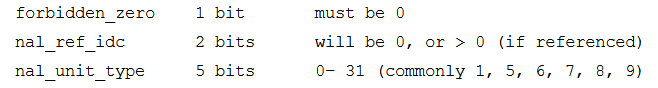
NALU payload
[variable size]
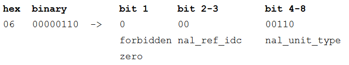
Although not comprehensive, the table below includes examples of commonly found NAL unit header bytes and how they are deciphered in order to identify the type of H.264 component contained within the NAL unit.
| NAL unit header (hex) | binary | bit 1 | bit 2-3 | bit 4-8 | |
|---|---|---|---|---|---|
|
|
|
forbidden zero |
nal_ref_idc |
nal_unit_type |
note |
|
06 |
00000110 |
0 |
00 |
00110 |
SEI |
|
65 |
01100101 |
0 |
11 |
00101 |
I Frame |
|
45 |
01000101 |
0 |
10 |
00101 |
I Frame |
|
41 |
01000001 |
0 |
10 |
00001 |
P Frame |
|
01 |
00000001 |
0 |
00 |
00001 |
B Frame |
|
67 |
01100111 |
0 |
11 |
00111 |
SPS |
|
68 |
01101000 |
0 |
11 |
01000 |
PPS |
The definition of a NAL unit does not include two important pieces of information that are critical for constructing an H.264 stream: when does a NAL unit express how many bytes it contains (i.e., how large is it), and how does one know when a NAL unit ends. Depending upon the implementation of H.264, there are different approaches to expressing the beginning and ends of NAL units in a byte stream. Two of these implementations are discussed below.
8. Annex B Implementation
Annex B is a common implementation3 of a video byte stream within H.264. This implementation is typically implemented in systems where there is a continuous video stream, or where the start and end times of a video are initially undefined. Another reason that a system would implement Annex B is that it allows for less processing than an AVCC implementation of H.264 (see section below) as it does not require packing the H.264 coded video stream into a multimedia format (e.g., MP4). In the Annex B implementation, video coded NAL units and non-video coded NAL units are strung together linearly within the stream. For example, this implementation is often found in Digital CCTV systems as well the native derivative files these systems generate.
The Annex B implementation introduces the concept of a “start-code prefix” as a new binary element included within a H.264 coded video stream. A start-code prefix is used to designate the start of a NAL unit in an Annex B H.264 byte stream, allowing a reader of the byte stream to identify the start of a NAL unit, and therefore to identify the single-byte NAL unit header that communicates the type of the NAL unit. The Annex B H.264 byte stream follows the structure of start-code prefix, NAL unit header, and NAL unit payload. The start-code prefix is either 3 or 4 bytes that are added before the header to signify the start of the next NAL unit. This will be represented in hexadecimal by either 0x000001 or 0x00000001.
After the start-code prefix, the NAL unit header is the next byte in the stream. The value within this byte defines the NAL unit type as described above. The bytes succeeding the NAL unit header are then described as the payload. The payload is the data that makes up either the VCL or non-VCL. For a video stream in Annex B, prior to the first VCL, IDR NAL unit, there must be two specific non-VCL NAL units. These will be the sequence parameter set (SPS) and the picture parameter set (PPS). The payload of each of these NAL units informs the decoder on how to interpret the VCLs that will follow.
After the SPS and PPS have been presented in the stream, the next VCL IDR NAL unit can be delivered to the decoder to allow picture data to be decoded and displayed. Once a VCL IDR NAL unit is completed, the next NAL unit start code will be present. See below for an illustration of how the start-code prefixes appear in the byte stream in the Annex B implementation.

In the Annex B implementation, the next IDR VLC will need to have another SPS and PP NAL unit preceding it.
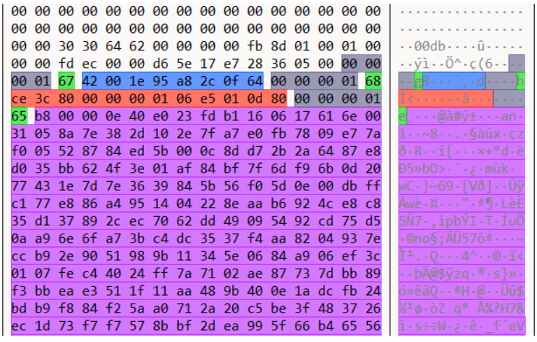
Example of the beginning of a video stream in Annex B. Grey is a start-code prefix, Green is a NAL unit header, Blue is an SPS NAL unit payload, Red is a PPS NAL unit payload, and Purple is an I-frame VLC NAL unit payload.
9. AVCC Implementation
For implementations that require the carriage of H.264 NAL units within an ISO base media file format wrapper, ISO/IEC 14496-154 defines the approach for packing H.264 coded video streams within the “MDAT” box of the wrapper5. This implementation differs from the Annex B approach in three distinct ways: 1) start-code prefixes are not employed; 2) SPS and PPS non- VCL NAL units are extracted from the H.264 byte stream and stored in a separate location in the file format wrapper (i.e., within the “avcC” box of the ISO base media file); and 3) a 1, 2, or 4 byte value (big-endian, unsigned integer) is introduced and prepended to all non-SPS and non-PPS NAL units that are stored in the “MDAT” box to signal the length of each NAL unit, as a replacement for the start-code prefix.
The “avcC” box is used within the ISO base media file to contain information about the H.264 data stored within the “MDAT” box as noted above. This “avcC” box will also contain information about how large the value will be that is preprended in the “MDAT” box to each NAL unit, (i.e., 1, 2, or 4 bytes in length). It also contains the SPS NAL unit(s) and the PPS NAL unit(s) that were extracted from the H.264 coded video stream before packing it into the “MDAT” box. The table below documents the expected contents of the “avcC” box when H.264 coded video is present in an ISO base media file.
| Structure Name | Length | Type | Endian | Hex Example | Interpreted Value |
|---|---|---|---|---|---|
|
Box Size |
4 bytes |
u32int |
Big |
h.00000033 |
51 |
|
Box Name |
4 bytes |
ASCII |
Big |
h.61766343 |
avcC |
|
Version Number |
1 byte |
u8int |
n/a |
h.01 |
Always 1 |
|
avcC:avc Profile |
1 byte |
u8int |
n/a |
h.64 |
profile = 100 |
|
avcC:avc compatibility |
1 byte |
u8int |
n/a |
h.00 |
compatibility = 0 |
|
avcC:avc level |
1 byte |
u8int |
n/a |
h.1F |
level = 31 |
|
avcC:reserved |
6 bits |
bit6 |
Big |
b.111111 |
all on, all the time |
|
avcC:NALULength
|
2 bits |
bit2 |
Big |
b.11 |
3 = 3+1 = 4 (NAL unit
size value = 4 bytes long)
|
|
avcC:reserved |
3 bits |
bit3 |
Big |
b.111 |
all on, all the time |
|
avcC:numberSPSs |
5 bits |
bit5 |
Big |
b.00001 |
1 |
|
avcC:SPSsize |
2 bytes |
u16int |
Big |
h.001A |
Next 26 bytes are the SPS NAL unit |
|
avcC:SPS |
variable |
byte |
n/a |
h.6764001FACD9 805005BB011000
00030010000003
0320F18319A0
|
SPS NAL unit |
|
avcC:numberPPSs |
1 byte |
8int |
n/a |
h.01 |
1 |
|
avcC:PPSsize |
2 bytes |
u16int |
Big |
h.0006 |
Next 6 bytes are the PPS NALU |
|
avcC:PPS |
variable |
byte |
n/a |
h.68E9784CB22C |
PPS NAL unit |
In an AVCC implementation of H.264, the examiner should look for SPS and PPS NAL unit data within the “avcC” box in the file as discussed above. An example hex analysis would look like the illustration below, which demonstrates the actual “avcC” box of a sample file, where the SPS NAL unit is highlighted in red and the PPS NAL unit is highlighted in green.

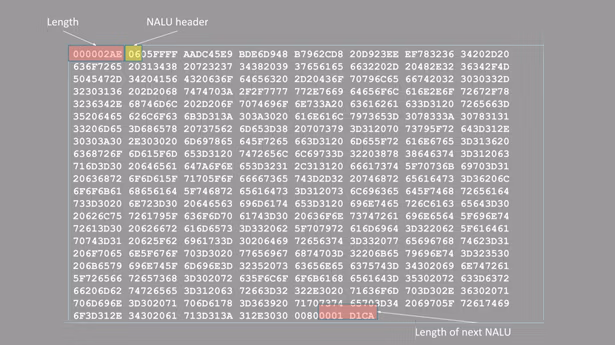
Within the “MDAT” box, the remaining NAL units from the H.264 coded video stream are found. Keeping in mind that the start-code prefix from Annex B is replaced with a 1, 2, or 4-byte value that communicates the size in bytes of each NAL unit in the stream, the implementation will look like the following illustration.
In sum, the full AVCC implementation of H.264 includes the following components spread out in two distinct locations within the ISO base media file format wrapper.

When media samples in addition to H.264 are included in an ISO base media file, these samples are interleaved in the “MDAT” box with the H.264 coded video stream, which will add complexity to the process of locating and extracting H.264 samples. To understand this scenario, review the ISO base media file format specification to understand how sample tables are used to document the location of each sample set within the “MDAT” box6.
10. Application in Forensics
For examiners, there are several uses of this understanding in practical application. Once an examiner understands and can interpret the video stream at the byte level, they should be able to locate and extract video information from unstructured datasets or proprietary video containers. For a fuller understanding of this process, see SWGDE Best Practices for the Recovery of Data from Security Digital Video Recorders Containing H.264 Data. Additionally, by being able to differentiate between the two implementations standard in H.264, it allows for the rebuilding of damaged files should the information be obfuscated or corrupted – the recording was not properly started or closed, or the manufacturer improperly segmented NAL units. This process may be addressed more in depth at a future point, however the process of manually parsing AVCC is time consuming and may be better conducted using automated tools.
Once a video stream is repaired or carved, either purpose-built software or open-source tools such as FFmpeg can be employed to place the H.264 video stream in a container that allows for more traditional playback and analysis. For more on utilizing FFmpeg, see the SWGDE Technical Notes on FFmpeg.
History
| Revision | Issue Date | Section | History |
|---|---|---|---|
|
1.0 DRAFT |
2019-09-19 |
All |
Initial draft created and voted by SWGDE for release as a Draft for Public Comment. |
|
1.0 DRAFT |
2019-09-29 |
— |
Formatting and technical edit performed for release as a Draft for Public Comment. |
|
1.1 |
2020-09-17 |
|
Voted for release as final publication |
1 These terms are sourced from ISO/IEC 14496-12 Section 3 – Definitions. Additional terms can be found within the standard.
2 There are circumstances when an I-frame or P-/B-frame is represented as multiple slices that constitute a single frame, then an access unit delimiter can be inserted to distinguish between coded slices that make up a single frame and those that make up slices within a frame. Because of this, a single NAL unit that contains coded picture does not always equate to a single frame; it may, instead, contain a slice of a single frame. However, the decoding of an access unit always results in a decoded picture, or a single frame
3 See ISO/IEC 14496-12 Annex B – Byte Stream Format for more information about full Annex B standard
4See ISO/IEC 14496-15 Information technology — Coding of audio-visual objects — Part 15: Carriage of network abstraction layer (NAL) unit structured video in the ISO base media file format.
5See ISO/IEC 14496-12 Information technology — Coding of audiovisual objects — Part 12: ISO base media file format for more information about the structure of ISO base media file format wrappers.
6 See ISO/IEC 14496-12 Information technology — Coding of audiovisual objects — Part 12: ISO base media file format for more information about the structure of ISO base media file format wrappers.
Version: 1.0 (September 17, 2020)