Disclaimer:
As a condition to the use of this document and the information contained therein, the SWGDE requests notification by e-mail before or contemporaneous to the introduction of this document, or any portion thereof, as a marked exhibit offered for or moved into evidence in any judicial, administrative, legislative or adjudicatory hearing or other proceeding (including discovery proceedings) in the United States or any Foreign country. Such notification shall include: 1) The formal name of the proceeding, including docket number or similar identifier; 2) the name and location of the body conducting the hearing or proceeding; 3) subsequent to the use of this document in a formal proceeding please notify SWGDE as to its use and outcome; 4) the name, mailing address (if available) and contact information of the party offering or moving the document into evidence. Notifications should be sent to secretary@swgde.org.
It is the reader’s responsibility to ensure they have the most current version of this document. It is recommended that previous versions be archived.
Redistribution Policy:
SWGDE grants permission for redistribution and use of all publicly posted documents created by SWGDE, provided that the following conditions are met:
- Redistribution of documents or parts of documents must retain the SWGDE cover page containing the disclaimer.
- Neither the name of SWGDE nor the names of contributors may be used to endorse or promote products derived from its documents.
- Any reference or quote from a SWGDE document must include the version number (or create date) of the document and mention if the document is in a draft status.
Requests for Modification:
SWGDE encourages stakeholder participation in the preparation of documents. Suggestions for modifications are welcome and must be forwarded to the Secretary in writing at secretary@swgde.org. The following information is required as a part of the response:
- Submitter’s name
- Affiliation (agency/organization)
- Address
- Telephone number and email address
- Document title and version number
- Change from (note document section number)
- Change to (provide suggested text where appropriate; comments not including suggested text will not be considered)
- Basis for change
Intellectual Property:
Unauthorized use of the SWGDE logo or documents without written permission from SWGDE is a violation of our intellectual property rights.
Individuals may not misstate and/or over represent duties and responsibilities of SWGDE work. This includes claiming oneself as a contributing member without actively participating in SWGDE meetings; claiming oneself as an officer of SWGDE without serving as such; claiming sole authorship of a document; use the SWGDE logo on any material and/or curriculum vitae.
Any mention of specific products within SWGDE documents is for informational purposes only; it does not imply a recommendation or endorsement by SWGDE.
List of Figures
Figure 1
List of Tables
Table 1. Approximate Focal Length (in mm) Needed for a Three-Foot Wide Field of View
Table 2. Typical Image Recording Rate for Different Time-Lapse Modes
Table 3. Images Recorded per Second by Each Camera in a Switched System for Different Time-Lapse Modes
Table 4. System Checks and Maintenance Schedule
1. Purpose
(Note: This document was previously released as SWGIT Section 4 – Recommendations and Guidelines for Using Closed Circuit Television Security Systems in Commercial Institutions.)
The purpose of this document is to provide recommendations and guidelines for the use of video security systems. For the purpose of this document, fixed-site surveillance cameras and recording devices will be discussed. In most cases, these basic principles and recommendations can be applied to any video system using surveillance cameras and video recorders. This document addresses analog and digital video systems. The intent of these recommendations and guidelines is to optimize image quality to facilitate the identification of unknown people and objects depicted therein.
The use of video security systems and the recording of security images is an accepted practice in commercial institutions, private residences, and other facilities. This practice can contribute to the investigation of criminal activity. It is the position of SWGDE that, in order to optimize the use of these systems, the following criteria should be met:
- Recordings must be preserved in a manner that permits law enforcement officials to recover the original images with a documented chain of custody.
- The number, placement, and type of cameras should be sufficient to provide adequate coverage and detail in the monitored area.
- There should be adequate, balanced lighting in the monitored area.
- Institutions should establish and follow a program of regular system maintenance.
- Institutions should have documented procedures to ensure that employees know what to do in the event of a criminal incident.
2. Scope
A video security system may include a single camera or multiple cameras. Coverage can include checkout areas, walk-up or drive-up automated teller machines (ATMs), public-service areas, entrance or exit doors, work areas, interior corridors or common building hallways, and exterior or interior parking areas.
A video security system may include cameras, a monitor to view the camera images, a recording device to capture selected images, and software, or a switching system, to control the method of selecting and storing images. Depending on the location and situation, video security systems may use an analog videocassette recorder (VCR), a digital video recorder (DVR), or a network video recorder (NVR) to record images from the cameras. Finally, a means of retrieving and storing images must be incorporated into the system.
This document addresses video security systems in the following four areas:
- Functional Requirements (Section 4)
- System Design (Section 4.1)
- System Maintenance (Section 5)
- Evidence Handling (Section 6)
3. Limitations
This document does not specifically address employee theft or other internal security issues, although some of the recommendations can be applied to those problems. Likewise, this document does not address live monitored surveillance systems or DVRs utilized for entertainment purposes (e.g., TiVo, DirecTV, Comcast, etc.).
These guidelines are not intended to replace or take precedence over other regulatory requirements in the specific jurisdiction of the facility to which these guidelines will be applied.
4. Functional Requirements
The purpose of these requirements is to increase the likelihood that images recovered from video security systems are sufficient to enable law enforcement officials to identify the people and objects of interest depicted.
In order to identify a person, specific individual features, such as the detailed shape of the eyes, ears, nose, mouth, and chin, must be distinguishable. Identification is facilitated if the ability to distinguish smaller features, such as moles, scars, tattoos, and freckle patterns, as well as the ability to derive measurements of these features, is possible. Likewise, identifying a vehicle requires that the license plate numbers or other identifying characteristics be distinguishable.
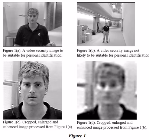
In Figure 1, the images on the left are more likely to allow for personal identification than the images on the right. The lower part of the figure shows the head of the subject from each image after it has been enhanced.
4.1 System Design
The ability of a video security system to record images that will be of greatest assistance to law enforcement depends on multiple factors, including the choice and placement of cameras and lenses, recorders, storage space, compression schemes, and data transmission. These factors are dependent on one another and must be coordinated. As an example, adding cameras to an existing system may require adjustments to the amount of storage or the rate at which images from each camera are recorded.
A careful survey of the facility in which the system will be installed must be completed and analyzed as an integral part of the total design process. A site plan documenting the location and field of view of each camera in the facility should be included as a part of this survey. Finally, upon installation, the system must be tested to confirm that images produced by the system as output (i.e., those that would be provided to law enforcement in the event of a criminal investigation) are of sufficient quality to maximize the likelihood of identifying people or objects depicted therein.
4.1.1 Components
Video security systems should include the following components, at a minimum: a camera or cameras, moveable and/or fixed; a recording device, including the means by which the recording may be extracted from the device; and a monitor. Consideration should also be given to any need for recording audio with the video from one or more cameras and any legal problems unique to audio recording. Guidelines for devices are addressed in the following subsections.
4.1.2 Cameras
Cameras used in video security systems should adhere to the following recommendations:
4.1.3 Number and Placement
The number of cameras needed by an institution will vary depending on a variety of factors, including the specific security needs of the institution and the monitored area(s). Care should be exercised to ensure that cameras are not located in places where they may be subject to tampering or accidental adjustments. Camera disabling and tampering can be minimized by using components that feature concealed wiring and protection of the camera and lens assembly from weather and/or physical damage.
The cameras’ fields of view should not be obstructed, nor should cameras be pointed directly at bright light sources, such as picture windows or spotlights. If bright areas cannot be avoided in a scene, cameras with backlight illumination or compensation adjustments are preferred to optimize the resulting image.
At minimum, there must be at least one camera for every exit. Exit cameras should be aimed toward the interior of the facility, and each one should be located where it can obtain an unobstructed frontal view of the head and shoulders of everyone exiting the facility. The lenses on exit cameras should be configured to have a depth of field that extends from three feet to at least ten feet from the camera, in order to provide images of exiting people that are in focus. Exit cameras that have a depth of field extending from three feet to more than ten feet will have the added benefit of providing overviews of the interior and head-to-foot views of people as they enter and exit the facility.
Cameras should be placed where they can record images with unobstructed views at each point of customer transactions, such as teller windows (walk-up and drive-through), cash registers, ATMs, or customer-service stations. There must be at least one camera at each point-of-customer transaction. Cameras should be adjusted to ensure that they are in focus at the location where a customer can be expected to stand. If a window or other security barrier is present, care must be taken to position the camera in a manner that minimizes reflection, glare, and other obstructions that can interfere with a clear view of the persons or objects being recorded.
Figure 1(a) illustrates a head and shoulders image that is preferable for the exit and transaction cameras. The camera lenses needed to achieve the fields of view are discussed in Section 4.1.8.
Cameras that provide overviews of the interior and exterior portions of a facility can be useful in an investigation, but cannot be relied on to provide images suitable for identification purposes. Therefore, in these guidelines they are considered to be of reduced importance. However, if the combination of the exit and customer transaction cameras does not provide complete coverage of the interior of the facility, then it is recommended that additional cameras be included for this purpose.
Exterior cameras intended to record images of vehicles should be placed to provide direct views of the vehicle so that the license plate is clearly visible and legible. Additional exterior cameras covering wider fields of view can provide additional vehicle information.
Moveable dome and pan/tilt cameras can be used to provide additional coverage through automatic alarm presetting and parking. Motion detection or door contact alarms can automatically initiate a camera preset providing a high-resolution view of the alarmed scene. This provides unmanned, additional target coverage. After a predetermined time, the camera can return to a preset parked position or to a scanning pattern to cover site locations not viewed by the fixed devices.
If the system contains a matrix switch with a joystick controller, a guard or observer can manually track a suspect giving a tightly zoomed, high-resolution image of the suspect. Variable speed control and automatic focus are recommended to facilitate smooth target tracking. When in the parked position, the unit can serve as an additional fixed camera.
Finally, in some instances, commercial institutions may find it useful to include monitored cameras as part of their overall security strategy. The video or images from such cameras are not intended to be recorded, but provide employees with a means to view areas in a facility that would otherwise be out of employees’ sight. However, in the event the video or images from these cameras are not recorded, the potential exists for the loss of valuable evidence.
4.1.4 Lighting
Poor lighting is the most common factor that degrades the quality of video images. Adequate, balanced lighting should be provided in areas viewed by the cameras. Particular care must be taken to ensure that the dynamic range present in a scene does not exceed the capability of the camera.
Strong backlighting or high-contrast lighting may cause the face of a subject to be obscured in shadow, making identification of a suspect from the image difficult or impossible. Likewise, spotlights can create both shadows and highlights on faces, making it difficult to determine if observed tonal variations represent actual features, such as facial hair, or are merely a product of the lighting. The use of non-infrared, high-dynamic range cameras and those capable of operating in low-light conditions should be considered to help improve the image quality.
As an example, ceiling-mounted fluorescent lighting that is well distributed throughout interior spaces would be preferred to the use of track-mounted spotlights.
Finally, different light sources have different color temperatures that will affect the apparent color of objects in a scene. Tungsten lamps impart a reddish tint to objects in a scene, whereas fluorescent bulbs can impart a greenish tint. Likewise, sodium lamps can make objects appear more yellow than they actually are. Most color video cameras can be adjusted to compensate for this, and many perform this function automatically.
A color video camera is considered balanced for a particular reference white when a neutral white card is placed in the camera’s field of view under normal illumination conditions and the red, green, and blue channels provide equal output levels. Therefore, interior color cameras should be balanced for white on installation and rebalanced if the type of lighting used is changed. However, because many commercial institutions will operate under conditions in which lighting is variable, white balance may not be possible at all times.
Infrared lighting can be used to provide improved low-light performance for monochrome cameras. Infrared lighting is not supported by standard color cameras as they filter out the infrared spectrum. If an infrared sensitive video camera is used, law enforcement officers should be made aware of this because an infrared sensitive video camera often reproduces clothing that appears to be dramatically differently when compared to images of the same clothing that were recorded with a video camera that is not sensitive to infrared.
A more complete set of technical guidelines for lighting is provided in Appendix A.
4.1.5 Black and White versus Color
Although some black and white video cameras may provide better image quality than color cameras, the information available in color images may provide important investigative information. Therefore, the choice of cameras is left to the commercial institution, depending on the intended use of the recorded images.
4.1.6 Resolution
In order to meet the SWGDE guidelines, analog video cameras must have an output resolution of at least 400 horizontal lines. Digital video cameras must have an output resolution of at least 640 pixels in the horizontal direction and 480 pixels in the vertical direction. The recording resolution of the video security system should match the resolution of the cameras. Cameras that have higher resolutions are strongly recommended.
4.1.7 Infrared Characteristics
The detectors used in black and white video cameras may be sensitive to a part of the infrared spectrum that is outside of the normal range of human visual perception. This can improve the ability of the camera to record in situations with low levels of visible light.
Objects in images acquired by infrared-sensitive cameras may not be accurately depicted in regards to tone (i.e., a light object may appear darker or dark object may appear lighter). Many cameras are equipped with filters that can mitigate this effect.
The use of infrared-sensitive cameras should be noted in the system documentation (see Section 5.1).
4.1.8 Lens, Focal Length, and Field of View
The selection of lenses will be dictated by the field of view to be covered by each camera and by the size of the camera’s detector.
For cameras placed to record images at point-of-customer transactions (e.g., a teller window) the area of interest (e.g., face) should cover approximately 15 percent or more of the camera’s field of view (based on the recommended minimum resolution found in Section 4.1.8). For an average human head, that is six inches wide; a three-foot wide field of view will meet this guideline. For a license plate width of approximately 12 inches, a six-foot wide field of view is sufficient.
The focal length necessary to achieve an approximately three-foot wide field of view for a given detector size and camera-to-subject distance is provided in Table 1. The camera must be in focus at the position of this subject.

(Note: Differences in the units used to describe these resolution recommendations are due to the differences in the industry standards used to describe these media.)
Cameras that provide overviews of interior and exterior locations should have their focal lengths selected to meet the field of view requirements of the facility. However, entrance/exit cameras should have sufficient depth of field to be in focus at distances of three feet and beyond to ensure that subjects entering/exiting the facility will be in focus. To gain depth of field, additional lighting to the area of interest should be provided.
4.1.9 Exposure Control
Cameras should be equipped with automatic mechanisms to ensure proper exposure under varying lighting conditions. Such mechanisms include, but are not limited to, automatic gain circuitry, day/night sensor switching, and lenses with automatic iris functions.
4.1.10 Camera Housings
Cameras may require coverings and environmental controls to protect them from the elements or tampering. Clear coverings placed in front of camera lenses will reduce image quality; therefore, unless there are specific environmental or security concerns that require camera housings, it is recommended that they not be used.
4.2 Electrical Power
Video security systems must be provided with adequate power. Backup power sources and surge protection should be included in the system design to ensure that recordings are preserved in the event of a power loss. Systems that require electrical power to preserve their recordings should have backup power sources sufficient to last for at least 30 minutes, until either the system power is restored or the system is shut down in a manner that preserves the recording. DVRs should also automatically restart in a preprogrammed operation mode on power up from the extended power outages.
Note: Abrupt power loss could result in the corruption/loss of the file system and/or video data.
When a video security system with automatic restart is used, there must be an on/off switch. This is to ensure that no data is lost following an incident that led to the recorder being purposely turned off to preserve the recording of the event.
Video security systems should be placed on isolated circuits that are properly grounded to reduce interference and signal degradation. If the system is on a long power run, outdoors, or in an area prone to electrical storms, special protection devices to control power surges and nearby lighting strikes are strongly recommended.
4.3 Bandwidth
The bandwidth provided for transmitting the video signal must be compatible with, and sufficient to meet, the resolution requirements listed below for the system’s recording device. Although bandwidth minimum standards do not guarantee acceptable video image quality, they do play an important part. To improve the likelihood of acceptable image acquisition, video cameras should have a signal bandwidth of at least 7MHz.
Bandwidth in digital video security systems also refers to the throughput capability of the network on which the system resides. The requirements for the network are dependent upon the number of cameras, resolution, and frame rate of the system, as well as other demands being placed on the network (e.g., non-video security traffic). Requirements for the network will vary depending on whether video is being recorded over the network, or transferred after being recorded locally.
4.4 Signal-to-Noise Ratio
One major problem with picture clarity is noise. Electronic noise is present to some extent in all video signals. Noise manifests itself as artifacts with in images, such as “snow” or graininess. There are several sources of noise: poor circuit design, heat, over amplification, external influences, automatic gain control, and transmission systems. Some video signal noise cannot be overcome in a reasonable manner. However, to improve the likelihood of acceptable image acquisition, video cameras should have a signal-to-noise ratio of at least 48dB. Further, the line loss between each camera and the multiplexer or recorder that the camera is connected to shall not cause the signal to fall below 45dB.
4.5 Recording System
Recording systems used in video security systems should adhere to the following minimum standards.
4.5.1 Recorder Security
Steps must be taken to ensure the physical security and integrity of the system’s recording device. Placement of the recording device in a restricted access location, such as a locked cabinet or room, is strongly recommended. Using a camera that records to an onboard SD card is also recommended. Note that proper environmental controls must be implemented according to the manufacturer’s specifications. For example, recorders require adequate airflow to prevent overheating.
Policies should be in place to ensure law enforcement can gain immediate access to the recorded images when necessary.
4.5.2 Recording Resolution for Analog Recording Systems
Analog videocassette recorders must record each image at a minimum line resolution of 240 visible lines. This resolution is typical of most VHS videocassette recorders. The use of videocassette recorders with higher line resolutions (e.g., S-VHS videocassette recorders and tapes) is strongly encouraged because this improves image quality. Analog systems meeting these minimum requirements are still suitable for use, however, their availability and use has declined.
4.5.3 Recording Resolution for Digital Video Recorders/Network Video Recorders
It is strongly recommended that digital video recorders or network video recorders using digital media for storage record each frame at a minimum resolution of 640 pixels in the horizontal direction and 480 pixels in the vertical direction. If images are recorded in field mode, then each field must be recorded at a minimum resolution of 640×240.
The recording resolution for a given DVR/NVR will vary depending on the specifications, configuration, and installation of the system. For example, higher resolution settings may decrease the recording time available, but generally will produce higher quality images.
It should be noted that, among other things, both the recording resolution of the system, the type and level of compression (see Section 4.5.4), and the resolution of the cameras (see Section 4.1.6) will determine the level of detail in the recorded video or images.
The Scientific Working Group on Digital Evidence strongly encourages the use of higher resolutions than those described above whenever possible.
4.5.4 Compression
Compression is a process in which the size of a digital file is reduced. Due to the large amount of information present in each video image, most digital video security systems use compression to reduce storage and transmission requirements.
Compression may be lossless or lossy. In lossless compression, all data can be retrieved in its original form. When data has been saved using lossy compression, it is not possible to recover all of the information.
In the event of an alarm-triggered mode (see Section 4.5.9), it is recommended that lossless compression be used to record the incident. If a system is incapable of lossless compression, it is strongly recommended that the lowest possible amount of compression be used in order to maximize the amount of information available to law enforcement.
Some manufacturers use nonstandard formats that require the use of proprietary software to view the video or images. Use of such software can prevent or hinder law enforcement from viewing or otherwise accessing these images. If such software is required, then steps must be taken to ensure its availability to law enforcement. Refer to SWGIT Section 7 – Best Practices for Forensic Video Analysis.
4.5.5 Analog Video Recording Speeds
Analog videotapes are usually recorded in one of three speeds: SP (standard play), LP (long play), or EP/SLP (extended play/super-long play). A T-120 tape recording at SP speed will record for a period of two hours, whereas a T-120 tape recording at LP speed will record for a period of four hours, and a T-120 tape recording at EP/SLP speed will record for a period of six hours. Changing the recording speed from SP to LP to EP/SLP play does not change the rate at which images are recorded.
4.5.6 Recording Rates and Time-Lapse
National Television Standards Committee (NTSC) video is recorded at a rate of approximately 30 frames per second. Each frame consists of two fields or images, producing an actual rate of 60 images per second. Any recording made at a rate of 60 fields per second is commonly referred to as a real-time recording.
Both analog and digital video security systems are capable of recording video at rates that are much lower than 60 images per second. This enables the recording of images over a longer period of time.
In digital video security systems, this is expressed as the recording (record) rate of the system. The recording rate may be configured for the entire system, or independent to each camera. For example, a ten (10) camera system could be configured to record twenty (20) images per second (ips). As noted above, depending on the system, this could result in each camera being recorded at 2 ips or 20 ips.
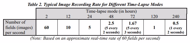
In analog video security systems, the recording rate is typically expressed as time-lapse rate. A single time-lapse rate is configured on and for the videocassette recorder. In situations involving multiple cameras, such as when using multiplexers, additional configuration can be made to capture additional images from certain cameras (see Section 4.1.2). The images per second captured by the recorder can be affected by the time-lapse rate (or mode), length of the recording media (e.g., VHS videotape), and the recording mode (described in the previous section). For example, using T-120 tapes, a VCR set in SP mode will record 30 frames (60 images) per second for two hours. With a time-lapse setting of 24-hours, a T-120 tape will run for twelve (12) times the normal two-hour tape length, and the VCR will record no more than five images per second. Table 2 provides the image-recording rate for a variety of common time-lapse settings under normal recording conditions.
Some analog time-lapse video recorders manufactured specifically for video security applications are designed to record a higher number of fields per second in different time-lapse modes than those reported in Table 2. For example, some high-density video recorders can achieve record rates of more than 20 fields per second in 24-hour time-lapse mode.
The recording rate of the system, whether digital or analog, should be configured to adequately capture the activity of interest in the coverage areas. When possible, areas which contain fast movement (e.g., cameras focused on register drawers) or otherwise important (e.g., entrances and exits) should be captured at a higher recording rate. For more information regarding camera placement and importance, refer to Section 4.1.3.
In order to meet SWGDE guidelines, video security systems must capture and record at least one complete field per camera per second. Any rate lower than this may result in inadequate coverage of events in the scene.
4.5.7 Switchers/Multiplexers
Facilities utilizing analog video security systems with more than one camera may choose to use a device that enables the recording of images from all of the cameras to a single recorder. The two most common devices used to do this are switchers and multiplexers.
Switchers, as the name implies, alternate among multiple cameras so that the output of the switcher at any one time is the signal from a single camera. Systems in which the output of a switcher serves as the input to the recording device will record images from each camera in succession. The time that it takes for a switcher to return to the same camera is called the camera interval. The reciprocal of this interval is referred to as the camera refresh rate. Therefore, a camera interval of one-half second would correspond to a camera refresh rate of two times per second.
A multiplexer takes the outputs from multiple cameras and adds an encoded signal that allows a picture from each camera to be viewed in succession (as with switchers) or simultaneously. The encoded data carried within the signal is typically proprietary, making it difficult to recover the recorded images, date, time, and other information without the proper hardware and software.
Many multiplexers and switchers allow users to view multiple cameras in a multiscreen mode, while also recording a full size image output of each camera. While multi-image viewing is acceptable, multi-image recording is not recommended.
In order to meet SWGDE guidelines, video security systems must not record in multi-image modes, because it significantly decreases the individual camera’s image resolution (size) and quality.
Given the requirement in Section 4.5.6 (recordings should capture at least one complete field per camera per second) the refresh rate for each camera in a system with one recorder will have a minimum value. As a reference, Table 3 relates the number of images per second, per camera for given time-lapse recording modes.
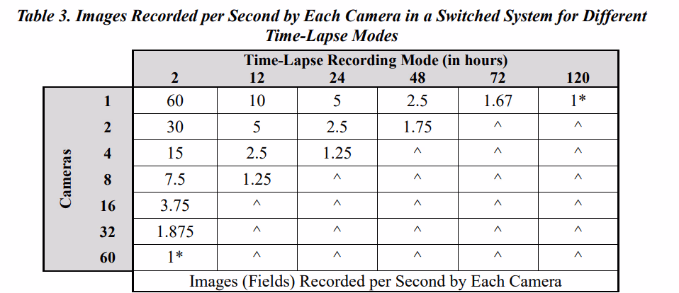
* Indicates limits fixed by the Scientific Working Group on Digital Evidence requirement of one image per camera per second.
^ Indicates this cannot meet the Scientific Working Group on Digital Evidence requirement of one image per camera per second.
The values reported in Table 3 assume a nominal real-time recording rate of 60 fields per second. As described in Section 4.5.6, some video security system recorders designed specifically for time-lapse applications are capable of exceeding the values reported in this table. Under such circumstances, it will be possible to record images from more cameras while still meeting the SWGDE requirement of one image per camera per second.
Most digital video security systems support the recording of multiple cameras with hardware integrated into the recording unit.
4.5.8 Recordings of Associated Text Information
Both analog and digital video security systems include the capability to associate text information, such as date, time, and camera identification, with the images recorded by the system. In some cases, transaction or personal information may also be recorded in association with image data. This is often accomplished by superimposing the text directly on the images.
Date, time, and camera information is useful in investigations and should be preserved. However, text that obstructs the view of subjects’ faces or vehicles’ license plates may hinder investigations and should be placed to minimize the effect on image content. Test recordings should be performed to ensure that this requirement is being met and that the information being recorded is accurate.
SWGDE strongly recommends that digital video security systems be configured so that associated text information is unalterable and preserved as data records or files that are linked to the respective images. In such cases where date and time, transaction, or personal information is recorded in digital systems along with the image stream, it must be possible for law enforcement to recover the images separate from this information.
For analog video security systems where it is not possible to separate personal or transaction data from the images, systems must be configured to record this information for one second or less for each instance (e.g., transaction) in which such data is required. If the text information is visible on the recorded video, then the text characters must be as small as possible while still being legible, and it must be possible to position the text anywhere on the screen to minimize the effect.
Each individual image and transaction data packet should have a date/time stamp associated with it. Whenever possible, the date/time stamp should be generated as close to the image source as possible. For example, when a camera is directly wired to the digital recording device at the same site, then time synchronizing the recorder is sufficient. However, when the camera is located remotely (in another city) and connected to the recorder by a wide area network (WAN), then the image may be delayed in transit. In those cases, it is highly desirable to associate the time stamp with the image at the source sensor (the camera) instead of at the recorder. A time-tag image file is then transferred over the WAN to the recorder. The trend toward using Internet Protocol (IP) cameras will facilitate this process where the IP camera is capable of accepting time synchronization input. The use of an industry standard time synchronization protocol is recommended.
4.5.9 Triggers & Alarms
In some situations, systems may include triggers that lead to the recording of images at a rate, or in a sequence, that differs from the normal operating mode. An example of this would be to change from time-lapse mode to real-time mode when triggered by an alarm button. Another example would be to include an otherwise inactive camera in the recorded sequence if motion was detected in that camera’s field of view.
If such a device is used, its use must not conflict with the recommendation in Section 4.5.6 (e.g., one field per second from every camera in the system must continue to be recorded at a minimum).
Unlike triggers, which are typically activated automatically (e.g., motion detection), alarms are usually activated manually during an incident such as a robbery.
In the event of alarm activation, law enforcement will seek to have the highest possible image quality. Therefore, in order to meet SWGDE guidelines, video security systems must have an alarm mode. The following system settings are required for the alarm sequence:
- Systems shall use lossless Currently installed systems that are incapable of lossless compression should be configured to record the alarm sequence at the lowest possible compression ratio, see Section 4.5.4.
- The recorder must have a buffer capable of retaining the five minutes of data prior to the alarm trigger.
- The system should record the cameras of interest at a rate of 15 images per second, while maintaining the same rate at which the system switches between cameras (e.g., more pictures per camera each second if time-lapse mode is normally used).
- Once triggered, the system should continue to record in this same manner until manually stopped by an authorized agent, according to the facility’s policies and procedures. Systems should be configured to prevent overwriting video from the incident that triggered the alarm. The recorder shall have sufficient storage to be capable of recording in this mode for a minimum of 30 minutes.
Furthermore, test recordings should be made to ensure that activation of a trigger or alarm does not have a harmful effect on the quality of the recorded images.
4.5.10 Retention of Recordings
It is recommended that analog videotapes be retained for a minimum of 31 days before being reused, and only be reused a maximum of 12 times. For ease of retrieval, each videotape should be sequentially numbered, and the dates and times recorded on each tape should be written on a label on the videotape.
Due to the nature of digital recordings, SWGDE recommends that recordings be retained for the longest time possible (minimum of 10 days) with the least amount of compression available in the system’s capabilities. Storage capacity to meet these needs must be considered.
Institutions should establish policies regarding the marking of removable media (e.g., VHS videotapes) so that the most recent date of recording will be documented.
Institutional requirements will dictate the length of time for which recordings must be retained.
4.5.11 Network Monitoring & Recording
Some video security systems allow for remote monitoring, recording, and device (e.g., camera) control over a network.
The images transmitted this way are often significantly compressed in order to meet bandwidth restrictions. As noted in Section 4.5.4, excessive compression severely degrades image quality.
In situations where remote monitoring is practiced, SWGDE strongly recommends that recording devices be installed at each local facility so that images may be recorded with minimal image compression.
When utilizing device control over a network, the response times experienced may not be equivalent to local control. Tests should be performed to ensure sufficient response time. Due to the increased load placed on the network in these situations (see Section 4.3), tests should be performed to ensure sufficient bandwidth is available. In order to obtain sufficient bandwidth, a dedicated network for video security may be required.
4.5.12 Digital Video Security System Export
Unlike analog videotape based video security systems, retrieving digital video footage is often not as easy as ejecting a videotape. The hardware and file formats vary greatly among digital video security systems.
The digital system should provide the capability to export a specific time period and/or camera views. Refer to SWGIT Section 7 – Best Practices for Forensic Video Analysis for further information regarding guidelines for export in the event of a criminal incident.
4.5.12.1 Devices
Digital recording systems must be capable of exporting exact duplicates of their recordings to a standard removable media format (e.g., CDs, DVDs). This is necessary so that law enforcement officials can obtain copies of the recorded digital files that are a bit for bit copy of the files stored on the system.
In order to meet SWGDE guidelines, video security systems using digital recorders must be configured to export to storage devices, including CD/DVD. In order to facilitate larger exports, the system must also include at least one standard port that supports the connection of external storage devices, such as Universal Serial Bus (USB).
Unless absolutely necessary, it is not recommended to output video from a digital video security system via an analog signal (e.g., recording to VHS videotape).
Write once media (e.g., CD-R) should be used whenever possible.
4.5.12.2 File Types
The format of most video security data is usually proprietary. Without the native file and proprietary software, it may be difficult to display the date, time, and other information with the recorded images. For this reason, proprietary file viewers should be included in the export, or otherwise available.
All export formats must maintain aspect ratios consistent with the original recording.
4.5.12.3 Video
It is important for the system to support the export of bit for bit copies of original video files.
The system should also support the export of video files in an open file format, such as uncompressed, nonproprietary AVI (audio video interleave).
4.5.12.4 Still Image
The system must support the export of single still image files in a standard lossless format (e.g., BMP or TIFF). Formats that use lossy compression (e.g., JPG/JPEG) should not be used unless a lossless format is not available.
4.6 Monitor/Display
For analog video recording systems, monitors capable of operating in an under-scan mode are strongly recommended. This capability permits the viewer to observe the entire field of view being recorded. For digital video recording systems, a digital display is strongly recommended.
5. System Maintenance
Video security systems should be maintained in a manner that ensures their proper function. Therefore, the following recommendations should be adhered to.
5.1 System Documentation
Institutions should maintain documentation regarding their video security systems that includes the following information:
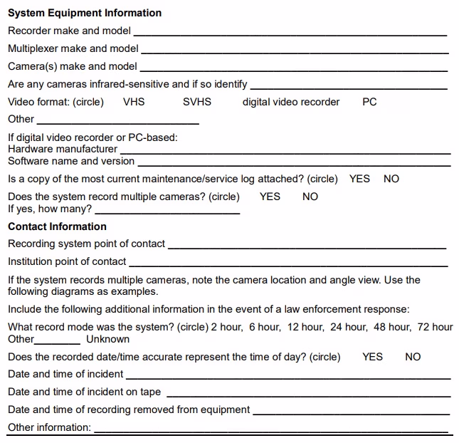
- Make and model of all system components, including recorders, cameras, lenses, and multiplexers/switchers. For digital systems, this information should include software and hardware information, including software version. If infrared-sensitive cameras are i use, their location should be documented. An example of a system information sheet is included in Appendix B. A photocopy of the maintenance record should be included.
- Adequate system documentation should be included at the This includes system manuals, retention schedule, keys, passwords, and instructions for downloading and outputting recordings.
- Point-of-contact information for system installer and/or system maintenance organization, to include at least two names and telephone numbers.
- Site plan showing all equipment placement (including recorders), as well as field of view for each camera. Appendix B includes an example of a site plan.
This information should be verified monthly and made available to responding law enforcement officials upon their arrival at the scene.
5.2 System Validation and Maintenance
Prior to use, systems must be validated to meet the requirements of this document. The systems must be capable of acquiring, recording, and producing output images that are of sufficient quality to enable law enforcement officials to identify the people and objects depicted therein. Revalidation of these requirements must occur every time the system is altered.
For example, if additional cameras are added to the system, the resulting video quality could be negatively impacted and should be verified.
A variety of system checks and maintenance are necessary at different times. If system errors are found, steps to correct them should be implemented.
A maintenance log must be maintained to document all system validation activities, checks, and maintenance activities.
Table 4 provides a calendar for these checks and maintenance items that should be recorded on a maintenance log.

5.3 Maintenance of Recording Media
All recording media has an expected usable lifespan. Based on that lifespan, policies should be developed to ensure that media is replaced before this period expires. For example, it is recommended that VHS videotapes be reused no more than 12 times and that they be replaced on an annual basis. The use of extended time-lapse mode may drastically shorten the life span.
For digital recording devices, manufacturer’s recommendations for maintenance and the device service-life replacement schedule should be observed. A regular ongoing (automated) inspection of hard drives should be conducted to ensure that the disk(s) is/are functioning properly and that there are no bad sectors or other hardware errors that could result in a loss of data. Other reusable media must be recertified no less frequently than the manufacturer’s guarantee period.
Steps must be taken to ensure that media is not mishandled or damaged. This includes keeping media away from magnetic fields, such as those generated by televisions, radios, and speakers. The media should be maintained at room temperature and out of direct sunlight. Media should not be stored in vehicles for an extended period of time.
6. Evidence Handling Procedures
This section addresses procedures to follow when law enforcement response is necessary pursuant to an investigation.
6.1 Documentation for Law Enforcement
The system documentation, as described in Section 5.1, including equipment information, site plan, passwords, contact information, and maintenance log, should be made available to responding law enforcement officials. Any additional pertinent information regarding the recording or the incident itself should be noted, such as incident time, record mode, and discrepancies between actual time and recorder time. Appendix B includes an example of documentation.
6.2 Handling Evidentiary Recordings
Following an incident involving immediate law enforcement response, it is necessary to ensure that the recorded images are secured. Unless the possibility exists that the images may be recorded over, the recording should not be stopped or reviewed until law enforcement officials arrive.
6.2.1 Analog Video Systems
Upon stopping a recording, the tape should be removed from the recording device and the recording tab immediately removed or shifted to the record-disabled setting. The name of the institution and identity of the person performing this function should be marked on the exterior of the cassette housing, along with the date and time of removal.
Personnel to assist in accessing the tape should be identified and made available prior to the arrival of law enforcement officials.
6.2.2 Digital Video Systems
The following steps should be followed:
- Upon stopping a recording, personnel qualified to assist law enforcement in recovering video from the video security system should be identified and made available (in person or by telephone) to offer technical assistance.
- Law enforcement officials will coordinate with appropriate personnel to view and retrieve the best video and/or image(s) prior to the officials’ departure from the scene.
- When immediate transmission or distribution is necessary from the scene, the video and/or image(s) should be made available by network, e-mail, CD/DVD, or other means. Images should be provided to law enforcement in the TIFF or BMP format. It is not recommended to solely provide JPG images to law enforcement unless absolutely necessary.
- If the facility uses a remote location for the storage of recorded images, then the facility will provide video and/or image(s) to an address designated by the law enforcement officials.
- The facility’s security personnel should produce at least two copies of the relevant images and video on CD-R, DVD-R, or other removable media in its original native format, as well as a nonproprietary format.
- In the event of alarm trigger incidents as described in Section 4.5.9, law enforcement would like all video and relevant data that were recorded five minutes before the alarm trigger, the entire incident, and five minutes after the incident. This is barring any outside circumstances when it is required to save a longer period of time (e.g., casing of the bank).
- If additional retrieval of video is warranted, law enforcement officials will notify the facility’s security personnel to secure the recording device, or retrieve additional video and/or images.
- When the relevant video, images, and data have been retrieved, each shall be labeled with the name of the institution and identity of the person performing this function, along with the date and time of removal. This information should not be written directly on the media but preferably on a label that is affixed to a protective container, such as a jewel case, sleeve, or clamshell enclosure.
7. References
Aldridge, J. CCTV Operational Requirements Manual Version 3.0. Police Scientific Development Branch (PSDB), United Kingdom Home Office, PSDB Publication number 17/94, ISBN 1 85893 335 8. (1994). Available: http://www.homeoffice.gov.uk/pcrg/psdb/publications/or_manual.pdf
Aldridge, J. and Gilbert, C. Performance Testing CCTV Perimeter Surveillance Systems. Police Scientific Development Branch (PSDB), United Kingdom Home Office, PSDB Publication number 14/95, 1995.
Atkinson, D. J., Pietrasiewicz, V. J., and Junker, K. E. Video Surveillance Equipment Selection and Application Guide, NIJ Guide 201-99. In Law Enforcement and Corrections Standards and Testing Program [Online]. (February 2000). Available: http://www.ojp.usdoj.gov/nij/pubs-sum/179545.htm
Brown, B. Crime Reduction: Closed Circuit Television in Town Centres: Three Case Studies.
United Kingdom Home Office Police Research Group – Crime Detection and Prevention Series Paper 68. (1995). Available: http://www.crimereduction.gov.uk/cctv1.htm
Diffley, C. and Wallace, E. CCTV: Making it Work. Training Practices for CCTV Operators. Police Scientific Development Branch (PSDB), United Kingdom Home Office, PSDB Publication number 9/98, ISBN: 1 84082 045 4. (1998). Available: http://www.homeoffice.gov.uk/pcrg/psdb/publications/cctv-9_98.pdf
Green, M. W. The Appropriate and Effective Use of Security Technologies in U.S. Schools. In: A Guide for Practical School Security Applications [Online]. (September 1999). Available: http://www.ojp.usdoj.gov/nij/pubs-sum/178265.htm
Griffiths, A. CCTV: Making It Work. Time and Date Displays. Police Scientific Development Branch (PSDB), United Kingdom Home Office, PSDB Publication number 13/98, 1998.
Mather, P. Guidelines for the Handling of Video Tape. Police Scientific Development Branch (PSDB), United Kingdom Home Office, PSDB Publication number 21/98, 1998.
Nichols, L. J. The Use of CCTV/Video Cameras in Law Enforcement, International Association of Chiefs of Police (IACP). (March 2001). Available: http://www.theiacp.org/documents/pdfs/Publications/UseofCCTV.pdf
Police Scientific Development Branch, Digital Imaging Procedure Version 1.0. Police Scientific Development Branch (PSDB), United Kingdom Home Office, PSDB Publication number 02/2002. (2002). Available: http://www.homeoffice.gov.uk/pcrg/psdb/publications/digimpro.pdf
Rason, J., Kent, T., Sall, I., Gugenheim, P., and Walker, S. Assessment of the ADVIS, IMPRESS, VIEW Video Enhancement System for the UK Police Service. Police Scientific Development Branch (PSDB), United Kingdom Home Office, PSDB Publication number 1/2000, 2000.
Scarman Centre National CCTV Evaluation Team, National Evaluation of CCTV: Early findings on scheme implementation – effective practical guide. United Kingdom Home Office Statistical Bulletin 5/03. (April 2003). Available: http://www.crimereduction.gov.uk/cctv32.htm
Security Industry Association, 1998-1999 CCTV for Public Safety Report, Security Industry Association, (August 1998). Available: http://www.siaonline.org/response.asp?c=storeproduct_59&r=1024
Tilley, N. Crime Reduction: Understanding Public Car Parks, Crime and CCTV: Evaluation Lessons from Safer Cities, United Kingdom Home Office Police Research Group – Crime Prevention Unit Series Paper No. 42. (1993). Available: http://www.crimereduction.gov.uk/cctv2.htm
Wallace, E. and Diffley, C. CCTV: Making it Work. Guidance on Recruitment and Selection Practice for CCTV. Police Scientific Development Branch (PSDB), United Kingdom Home Office, PSDB Publication number 8/98, 1998.
Wallace, E. and Diffley, C. CCTV: Making it Work. CCTV Control Room Ergonomics. Police Scientific Development Branch (PSDB), United Kingdom Home Office, PSDB Publication number 14/98, 1998.
Appendix A: Technical Guidelines for Lighting
In this document, illuminance is measured in Lux. Some older documents and references may refer to the measurement in footcandles (one footcandle is approximately equal to 11Lux).
To provide good-quality camera images, a minimum of 275 to 333Lux of illumination should be provided in the customer areas, office areas, hallways, stairways, and exits where there is camera coverage.
Exterior self-service facilities, such as automated teller machine vestibules or drive-up lanes, should have a minimum of 110Lux of illumination 24-hours daily to ensure good image quality.
Exterior areas, such as sidewalks, entrances, night depository areas, that have camera coverage should have a minimum of 55Lux of illumination.
Parking lots with camera coverage should have a minimum of 11Lux of illumination at ground level.
Supplementary surface lighting may be necessary for adequate illumination for the face of anyone using an automated teller machine or other self-service resource.
Appendix B : System Documentation and Site Plan Examples
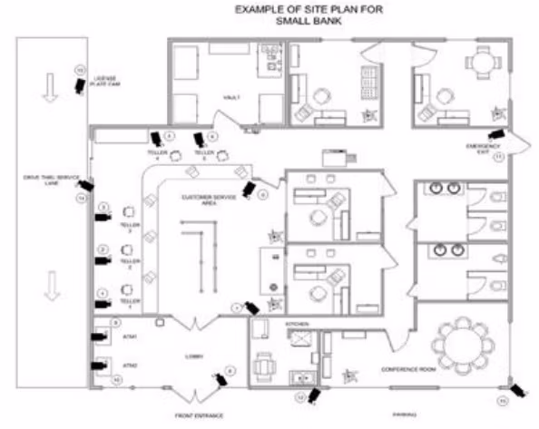
Camera 1: Teller one, facing east
Camera 2: Teller two, facing east
Camera 3: Teller three, facing east
Camera 4: Teller four, facing south
Camera 5: Teller five, facing south
Camera 6: Customer-service area, facing south-west
Camera 7: Customer-service area, facing north-west
Camera 8: Lobby, facing north-west
Camera 9: Lobby automated teller machine one
Camera 10: Lobby automated teller machine two
Camera 11: Emergency exit, facing west
Camera 12: Parking lot, south side of building
Camera 13: Parking lot, south-east corner of building
Camera 14: Drive-through service lane, facing west
Camera 15: Drive-through service lane, facing south
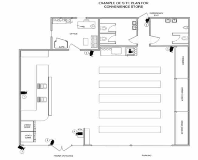
Camera 1: Clerk and check-out area, facing east
Camera 2: Front door entrance, facing north
Camera 3: Outside of office, facing south
Camera 4: Freezer area, facing south
Camera 5: Emergency exit, facing south
Camera 6: Automated teller machine, facing west
Camera 7: Parking lot, facing south-east
History
| Revision | Issue Date | Section | History |
|---|---|---|---|
|
1.0 |
06/01/2015 |
All |
Original working draft created. Voted for release as a Draft for Public Comment. |
|
1.0 |
06/20/2015 |
All |
Formatting and tech edit performed for release as a Draft for Public Comment. |
|
1.0 |
09/16/2015 |
All |
Comments received and incorporated into the document. Added comment to Section 5.5.1. Grammatical change made to Figure 1.
SWGDE voted to release as an Approved Document.
|
|
1.0 |
09/29/2015 |
All |
“Section 3 – Definitions” was removed and the terms were moved to the latest iteration of the SWGDE Glossary as part of final publication process. Formatting and technical edit performed for release as an Approved Document. |
Version: 1.0 (September 29, 2015)