14-f-005
Disclaimer:
As a condition to the use of this document and the information contained therein, the SWGDE requests notification by e-mail before or contemporaneous to the introduction of this document, or any portion thereof, as a marked exhibit offered for or moved into evidence in any judicial, administrative, legislative or adjudicatory hearing or other proceeding (including discovery proceedings) in the United States or any Foreign country. Such notification shall include: 1) the formal name of the proceeding, including docket number or similar identifier; 2) the name and location of the body conducting the hearing or proceeding; 3) subsequent to the use of this document in a formal proceeding please notify SWGDE as to its use and outcome; 4) the name, mailing address (if available) and contact information of the party offering or moving the document into evidence. Notifications should be sent to secretary@swgde.org.
It is the reader’s responsibility to ensure they have the most current version of this document. It is recommended that previous versions be archived.
Redistribution Policy:
SWGDE grants permission for redistribution and use of all publicly posted documents created by SWGDE, provided that the following conditions are met:
- Redistribution of documents or parts of documents must retain this SWGDE cover page containing the Disclaimer and Conditions of Use.
- Neither the name of SWGDE nor the names of contributors may be used to endorse or promote products derived from its documents.
- Any reference or quote from a SWGDE document must include the version number (or creation date) of the document and also indicate if the document is in a draft status.
Requests for Modification:
SWGDE encourages stakeholder participation in the preparation of documents. Suggestions for modifications are welcome and must be forwarded to the Secretary in writing at secretary@swgde.org. The following information is required as a part of any suggested modification:
- Submitter’s name
- Affiliation (agency/organization)
- Address
- Telephone number and email address
- SWGDE Document title and version number
- Change from (note document section number)
- Change to (provide suggested text where appropriate; comments not including suggested text will not be considered)
- Basis for change
Intellectual Property:
Unauthorized use of the SWGDE logo or documents without written permission from SWGDE is a violation of our intellectual property rights.
Individuals may not misstate or over represent duties and responsibilities of SWGDE work. This includes claiming oneself as a contributing member without actively participating in SWGDE meetings; claiming oneself as an officer of SWGDE without serving as such; claiming sole authorship of a document; use the SWGDE logo on any material or curriculum vitae.
Any mention of specific products within SWGDE documents is for informational purposes only; it does not imply a recommendation or endorsement by SWGDE.
Table of Figures
Figure 1. Example of a hand-held skimmer
Figure 2. Example of an altered hand-held skimmer
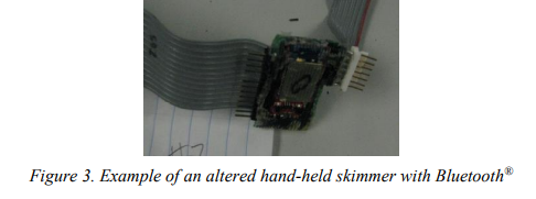
Figure 3. Example of an altered hand-held skimmer with Bluetooth®
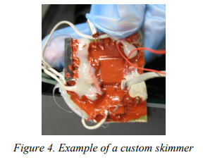
Figure 4. Example of a custom skimmer
Figure 5. Example of a custom skimmer (door)
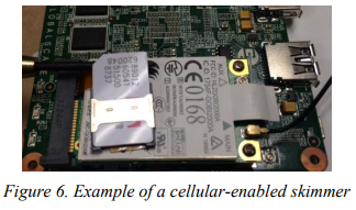
Figure 6. Example of a cellular-enabled skimmer
Figure 7. A Bluetooth® custom skimmer
Figure 8. A Bluetooth® custom skimmer secreted inside a gas pump
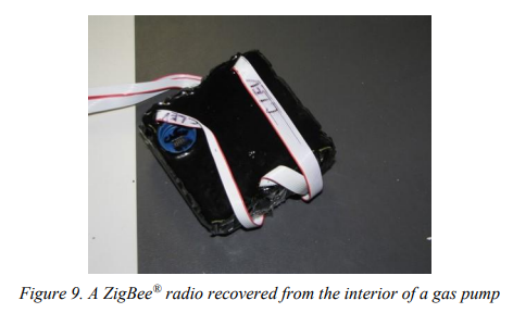
Figure 9. A ZigBee® radio recovered from the interior of a gas pump
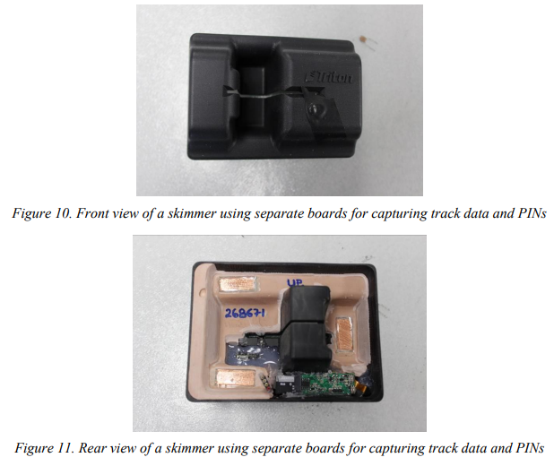
Figure 10. Front view of a skimmer using separate boards for capturing track data and PINs
Figure 11. Rear view of a skimmer using separate boards for capturing track data and PINs
Figure 12. A skimmer that is inserted into an ATM card slot
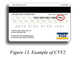
Figure 13. Example of CVV2
Figure 14. Example of keypad overlay
Figure 15. Example of an inline skimmer
Figure 16. Example of an analog based skimming device
Figure 17. Wires connected to a small flash chip
Figure 18. Wires connected from flash ship to chip reader
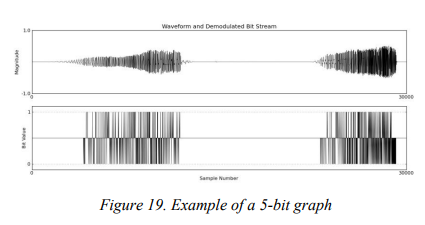
Figure 19. Example of a 5-bit graph
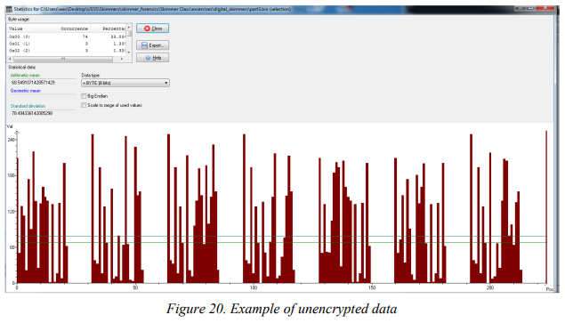
Figure 20. Example of unencrypted data
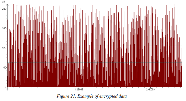
Figure 21. Example of encrypted data
Figure 22. Example of unpacked BCD data
Figure 23. Bluetooth® enabled skimmer
Figure 24. Bluetooth® module uncovered
Figure 25. Module outlined, antenna identified
1. Purpose
The purpose of this document is to describe best practices for seizing, acquiring, and analyzing data contained within magnetic card readers, and related transmission modules, capable of acquiring and storing personally identifiable information (PII) in an unauthorized manner. As a skimming device is not typically deemed contraband, it is the responsibility of the investigator/examiner to determine if the device was used illegally.
2. Scope
This document is intended for computer forensic practitioners conducting skimming device examinations. While the examination of a skimmer can render information about the subject of the investigation, the primary purpose of the examination, and therefore this document, is the retrieval and legible presentation of data stored on the device. Further details regarding the analysis of skimming devices as well as the data extraction and analysis of transmission modules is available in SWGDE Test Method for Skimmer Analysis – Analog Devices, SWGDE Test Method for Skimmer Analysis –Digital Devices, SWGDE Test Method for Bluetooth® Module Extraction and Analysis.
3. Limitations
Skimmers present unique examination challenges due to:
3.1 Rapid changes in technology;
3.2 Difficulty of device disassembly;
3.3 Use of alternate/repurposed components;
3.4 Use of encryption and/or examination countermeasures;
3.5 Multiple data encoding/modulation formats;
3.6 Prevention of chip identification by obfuscation of the device;
3.7 Lack of availability of training and documentation;
3.8 Lack of chip information/documentation;
3.9 Lack of chip adapters available for chip reading;
3.10 Expense of available equipment used in chip removal and reading;
3.11 Lack of software’s ability to support reading chip data;
3.12 Lack of commercially available software to analyze data extracted from skimmers.
4 Skimmer Examples
4.1 Hand-Held
Manufactured primarily for legitimate uses, e.g. registering attendance at a conference, handheld skimmers can also be used for illegitimate purposes, e.g. a collusive waiter that will skim customers’ credit cards.

4.2 Altered Hand-Held
It is common for commercial skimmer devices to be dismantled and used for parts (cannibalized). These devices are commonly seized from automated teller machines (ATMs), bank point of sale terminals, and gas pumps (see Figure 2). Commercial skimmers can be altered by adding wireless functionality, e.g. the addition of a Bluetooth® module (see Figure 3) used to remotely download stolen track data.

4.3 Custom
Custom manufactured devices use many different circuit designs (see Figure 4) and typically employ varied data encoding, modulation, and encryption schemes. These skimmers can be combined with a pinhole camera or a keypad overlay to capture the personal identification number (PIN) of the account holder.
As it is common in some larger metropolitan areas for ATMs to require a customer to use their account card for entry to a vestibule, subjects can implant foreign circuitry into the door reader (see Figure 5).

As previously noted, skimming devices may have the capability to output captured data via wireless communication methods (see Figure 6). These devices transmit their data in real-time or batch mode. Transmission protocols of these devices vary.
Similar to the altered handheld devices, custom skimmers can use Bluetooth® transmission technology (See Figure 7 and Figure 8).


In addition to Bluetooth and Global System for Mobile Communications (GSM) modules, skimmers can be remotely accessed through other transmission technologies, to include ZigBee® radio (See Figure 9).
Skimmers used on ATMs typically will capture both the data on the card and a user’s PIN number. As noted above, the method to capture the user’s PIN could be a completely different device, but even if that is true, the PIN information could be sent to storage on the same skimming device that is capturing the track data (see Figure 10). That information can be saved on flash chip(s) or a secure digital (SD) card, as seen in Figure 11.
While some ATM skimmers may be affixed to the front of an ATM, others are secreted inside the card slot (See Figure 12). Many of these types of skimmers will read data from a chipenabled card. Note: Just because data is skimmed from a chip, does not mean that the subject can use that data to create future, fraudulent transactions.

5 Card Data/Structure
Understanding the manner in which credit and debit cards store their data is important. The ability to decode skimmer-stored information relates to how data is stored on the magnetic stripe of a card.
5.1 Fundamentals of Track Data
The International Standards Organization (ISO) created ISO/IEC 7812 [1], which specifies, “a numbering system for the identification of issuers of cards that require an issuer identification number (IIN) to operate in international, inter-industry and/or intra-industry interchange.”
The primary account numbers are generally 15 or 16-digits in length, but can be as short as 12 (Maestro) or as long as 19 (China UnionPay). Credit card companies have reserved prefixes, for example, American Express cards begin with a “34” or “37”. Credit card processors use the Luhn algorithm, see [1], to ensure the integrity of the primary account number (PAN).
Applications such as access control, identification, and driver licenses have developed their own custom formats for each track. This capability to reformat the content of each track has allowed magnetic stripe card technology to expand into many industries. As defined for financial industry applications, the magnetic stripes carry three tracks of data.
5.1.1 Track 1
Track 1 contains alphanumeric information for the automation of airline ticketing or other transactions in which a reservation database is accessed. In addition to the account number and expiration date, this track contains the account holder’s name.
5.1.2 Track 2
Track 2 contains numeric information for the automation of financial transactions. While this track does not contain the account holder name, it does contain the electronic card verification value (CVV). This track is read by systems that require a PIN, e.g. ATMs.
5.1.3 Track 3
Track 3 contains information that is intended to be updated (re-recorded) with each transaction, e.g. cash dispensers that operate off-line. This track is rarely used and is not of forensic value in most financial fraud investigations.
5.2 Card Verification Value (CVV)
This code is recorded on the second track of a card and used to verify the card is present during a transaction.
5.3 Card Verification Value 2 (CVV2)
This code is a three- to four-digit number printed on the back of a card (see Figure 13). It was designed to help curb fraud in “card not present” transactions, such as Internet purchases.
5.4 Debit Cards
When skimmed, debit cards and credit cards convey similar data. However, debit cards are different from credit cards as the account is directly linked to fund availability in a bank (or otherwise stored) account. Debit cards present an attractive target for skimming, as compromised accounts can be converted directly into cash as opposed to goods and services.
6 Collection
6.1 Seizure
Devices should be collected and protected in the same manner as flash memory devices (refer to ASTM E2763 Standard Practice for Computer Forensics and SWGDE Best Practices for Computer Forensics [2], [3]). Associated cables, documentation, and software should also be collected.
6.1.1 Specific Skimmer Considerations Related to Seizure
- 6.1.1.1 There is a possibility of two devices being used to make up the skimmer, one device capturing card track data and a separate device capturing PINs, e.g. video and keypad overlay.
- 6.1.1.2 If a device is wired into something like a gas pump, it is most likely using power from the pump. Removing the device from that type of power connection will not affect the examination. If a battery is observed on a skimmer, leave the battery in place, unless there will be a significant delay before examination, i.e. more than a month.
- 6.1.1.3 If the skimmer is using a universal integrated circuit card (UICC) or SD card, it should be removed at the time of seizure.
- 6.1.1.4 If a device uses video and/or audio recording to capture information, that recording may continue after the device is seized.
- 6.1.1.5 Identifying parasitical devices can be challenging, as they are, by their nature, designed to be hidden. These include recording devices hidden under keypads and those placed in-line with a legitimate card reader (see Figure 14 and Figure 15). Removal of these devices can be destructive in nature and should be done cautiously.


6.2 Handling Evidence
Evidence should be handled according to laboratory policy while maintaining a chain of custody and by using best practices (refer to ASTM E2763 Standard Practice for Computer Forensics and SWGDE Best Practices for Computer Forensics [2], [3]).
7 Technical Background
As skimmers are often unique in design and implementation, examination processes vary depending upon the category and/or type of device.
When considering retrieving stored account information, due to differences in acquisition and analysis, skimmers can be broken down into two general categories, analog or digital.
The processes used in examinations vary depending on the device itself and the manner in which the stored information is encoded. While many skimmers will be manufactured with the capability of remotely downloading skimmed account data by the subject, that functionality does not typically change the way skimmed account information is stored on the skimmer or acquired by the examiner. Acquiring and analyzing Bluetooth® module artifacts is completed separately from processing the skimmer for stolen account data (see Section 11 Bluetooth® Modules)
8 Acquisition – Account Data
All skimming devices read magnetically-stored data on a card. This process is accomplished by means of an electromagnetic head, similar to that found in an audiocassette tape player. As the card is manually swiped through the device, the head converts the magnetic information on the card into an electrical signal of time-varying voltage, which may be passed to other signal processing components. Devices that store that waveform without further processing are referred to as “analog” devices. “Digital” devices further process the waveform.
8.1 Analog Skimming Devices
Analog skimming devices capture the analog magnetic signal on the card stripe to a digital waveform in flash memory. This signal is encoded according to the ISO/IEC 7811 suite of standards [4] but is otherwise similar to an audio waveform. The resulting file extracted from a device is similar to an audio file and significantly larger than a decoded bit-string of account data. Recovery of the encoded data requires further processing.
8.1.1 Identification
Recognizing an analog skimmer is important, as the method of extraction differs from that of a custom, digital skimmer. Identification of an analog skimmer can be made by either recognizing the cannibalization of an MPEG-2 Audio Layer III (MP3) device and/or by recognizing the unusually large storage capacity of the device’s flash memory chip (see Figure 16). As an example, a typical digital skimmer uses a flash chip in the area of two megabytes of storage, an analog skimmer typically contains a flash storage chip in the two gigabytes or more range.

8.1.2 Extraction
Many analog skimmers originated as other devices, e.g. MP3 sunglasses. Therefore, an examiner may extract data from the device using its built-in universal serial bus (USB) mass storage mode. As it is common for a person constructing the skimmer to remove the USB header, the examiner must recognize this architecture and solder a header or leads on the device to facilitate communication. Once the header is attached, the examiner creates an image using traditional computer forensics imaging techniques and software (refer to ASTM E2763 Standard Practice for Computer Forensics and SWGDE Best Practices for Computer Forensics [2], [3]).
8.2 Digital Skimming Devices
Digital skimming devices pass the analog swipe waveform to an ADC to produce a digital waveform, which is stored and coded in flash memory. Digital skimmer devices accept input via a magnetic stripe reader like analog skimmers; however, once the skimmer’s processor receives the waveform, the signal is decoded with logic before being stored in flash memory. Data can be stored in a variety of formats, which might or might not be ciphered or encrypted.
8.2.1 Chip Identification
Custom skimming devices can be complicated in nature. Their design can be developed using new and/or cannibalized circuits/chips. The main components of chip identification are the manufacturer and chip model numbers of both the microcontroller and flash chips. It is important to document/photograph them before removal, as extreme temperatures can remove identification markings. In cases where the identification number is worn or difficult to read, a microscope might be required. Additionally, applying a non-reactive and easily removed solution, such as isopropyl alcohol, can make identification numbers easier to read.
8.2.2 Chip Removal
As skimming devices typically do not have a universal and dependable method to connect to and download skimmed account information (other than USB used by analog devices), an examiner should remove the data storage chip and then read the information stored therein. The microcontroller might also need to be removed and read to understand the encoding or encryption methods used by the device. Unfortunately, code protection may prevent the extraction of data from a device’s microcontroller.
The chips should be properly removed from the circuit board in a manner that ensures they are not damaged. Removal should only be performed by properly trained and experienced personnel. Methods of extraction include hot air, infrared, and chip polishing/lapping/milling. Methods that require the entire chip being removed at once are preferred, as they reduce the chance of physical damage induced by prying and bending pins and/or destroying connection pads (refer to SWGDE Best Practices for Chip-Off and SWGDE Tech Notes regarding Chip-off via Material Removal Using a Lap and Polish Process [5], [6]).
8.2.3 Chip Connectivity and Reading
There are several chip readers commercially available, with each reader possibly supporting a wide array of chips. Most of the time, the examiner will need to use a chip socket adapter that matches the chip package. However, on certain smaller chips, connectivity between the chip and the reader may be established through a series of wires soldered to the chip pins and inserted either directly into the reader, or via a generic Zero Insertion Force (ZIF) socket (see Figure 17 and Figure 18). Note: despite being able to complete the mechanical connection, a chip programmer may require the use of a matching socket adapter presumably for marketing reasons.

Once properly connected, a chip can be read using vendor provided software. The extracted data should be saved, write protected, and hashed prior to analysis. Analysis should then be performed on a working copy (refer to SWGDE Best Practices for Chip-Off [5]).
As previously mentioned, custom skimming devices may use a wireless technology, e.g. ZigBee® , which the subject uses to access account information skimmed and stored on the skimmer. It might be possible to extract data from these devices through that same wireless connection, if certain pairing data is known to the examiner, e.g. the specific channel on which a ZigBee® radio skimmer is broadcasting. Caution should be taken regarding pairing with a Bluetooth®-enabled skimmer as that will overwrite the last connected MAC address artifact.
9 Data Analysis – Account Data
9.1 Data Format Types
Relative to skimmer data analysis, there are two types of recordings, analog and digital. Digital skimmer data recordings consist of several different sub-types that will be discussed later. The ISO/IEC 7812 and 7813 track data formatting assists the examiner in analyzing the extracted data, as it provides a set of rules to which the decoded information should conform [1], [7]. As most card readers are bidirectional, care must be taken during the analysis phase to account for numbers sequenced forward and backward, while also ensuring duplicate account numbers are not repeated in a report of findings.
9.1.1 Analog Skimmer Data
Due to the encoding mentioned above, file(s) present on an analog skimming device will not be recovered via automated credit card finder scripts, e.g. regular expressions. The extracted files require processing by the examiner. Most commonly, the file(s) extracted from an analog skimmer will be in the form of a Waveform Audio File Format (WAV) audio file. Continuing, the examiner will be required to carve the track data from the extraction file, convert the file into a format such as 16-pulse-code modulation (PCM) or adaptive differential pulse-code modulation (ADPCM), then decode the data with a clock-recovery algorithm with noise threshold activation. For a graphical representation, see top of Figure 19). The bit stream is used to decode to actual account numbers, i.e. high = 1, low = 0, in 5-bit American Standard Code for Information Interchange (ASCII) encoding, big or little endian.
9.1.1.1 Validation and Scripting
Analog skimmers typically capture the second track on a magnetic card. Track 2 is encoded using 5-bit ASCII (4-bit odd parity per American National Standards Institute (ANSI) Standard X4.16 [8]) and the account information follows a start sentinel of 11010.
The examiner would examine the bottom part of the graph in Figure 19 (representing the bits decoded from the waveform with a proper noise threshold) and attempt to locate the start sentinel (11010) and account number to determine if the results were accurate. Once verified that the process is appropriate for realizing account numbers, the examiner can automate the process through scripting.
9.1.2 Digital Data
Skimmed data can be stored and encoded, ciphered, or encrypted in a wide variety of formats. Common encoding formats include 8-bit ASCII, 5-bit ASCII, and Little Endian Binary-Coded Decimal. Common ciphering and encryption practices vary in their confusion/diffusion implementation. In some cases, single byte exclusive or (XOR) ciphers are used, others implement cryptographically sound algorithms, such as Advanced Encryption Standard (AES). Encrypted storage represents a significant challenge to the examination. As such, the use of statistical analysis on the extracted data is an important first step in determining if information read from a skimmer is simply encoded/ciphered or encrypted. Data that is encrypted typically exhibits higher levels of diffusion than encoded/ciphered data, resulting in byte values being more evenly distributed (see Error! Reference source not found.0 and Error! Reference source not found.1).
9.1.2.1 8-bit ASCII
The majority of hex viewers have the ability to display data by default in both base 16 hexadecimal and 8-bit ASCII formats. A skimmer designed to store account information in 8-bit ASCII makes data identification simple, e.g. 4271585934020341. If the data is stored in 8-bit ASCII, an examiner may find it efficient to run a command line tool against the extracted data in order to easily export from the image ASCII word groupings, i.e. account data.
9.1.2.2 5-bit ASCII
A skimmer that records account data in this type of encoding is best confirmed using a tool that displays data in Base2 (Binary).
- 9.1.2.2.1 Once viewed as binary, the examiner can search for a 5-bit account number start sentinel (11010, or 01011 if a reverse swipe).
- 9.1.2.2.2 If a start sentinel is located, the examiner can decode the binary characters following (or proceeding, if it was a backwards swipe) the start sentinel, checking both big and little endian byte order, searching for possible account numbers, verified by conformance to the Luhn algorithm. The range of binary characters varies according to the potential account number, e.g. 80 bits (16-digit account numbers multiplied by 5 bits) for a Visa or MasterCard account number.
- 9.1.2.2.3 If the examiner is able to recover a valid (per Luhn) account number, then the rest of the data can be decoded using an automated process scripted using these parameters.
9.1.2.3 Unpacked Binary-Encoded Decimal (BCD)
The BCD encoding scheme is discernible using traditional hex viewing software. If the data is stored with unpacked BCD encoding, the account number will be displayed in hexadecimal with a header value of 0x21.
- 9.1.2.3.1 The account number data following the header will be 12 to 19 bytes in length followed by an indeterminate number of 0x00 values (padding).
- 9.1.2.3.2 The next account number will begin with a 0x21 header, followed by the second account number, etc. See Figure 22 for an example showing two fictitious account numbers (Red = Header; Green = Account Number; Orange = Padding). Figure 22 below, depicts unpacked BCD data for the following account numbers: 4344562104567443 and 34563210876543011.
- 9.1.2.3.3 Once successfully identified, the examiner can then check the validity of the account numbers using the Luhn algorithm.

9.1.2.4 Ciphered/Encrypted Data
As opposed to the use of encryption on an entire hard drive, the analysis of an encrypted skimmer is assisted by the fact that there is a predefined structure of the plain text of the extracted information [1], [7], unless the format was changed prior to encryption. However, the decoding of the information is still limited to the complexity of the encryption used. For instance, data that is encrypted with a 2-byte XOR cipher is manageable, while data encrypted with AES represents a much harder problem.
In the situation where the stored data is obscured with an XOR cipher (or equivalent level of encryption), using the known structures [1], [7], an examiner can construct a cryptanalysis system based on mathematical equations, i.e. algebraic cryptanalysis. An example of such is the creation of Boolean polynomials that describe aspects of unencrypted, true account numbers. For a polynomial to be true, it must equal zero. As such, if one were to write a polynomial for an account number structure, such as every Track 2 character has an odd parity bit as its fifth bit, the equation would look like: pi + pi1 + pi2 + pi3 + pi4 + 1 = 0 (where i, the first bit of the character, is always true). Another polynomial specific to XOR is regarding the basic XOR equation itself: pi⊕ kj = cj (where pi = plain text, kj = the key, and cj = the cipher text). As every Boolean polynomial defined must equal zero, both sides of the equation are XOR’d by cj resulting in: pi + kj + cj = 0.
Additional equations could include the following: key restriction to printable ASCII; decimal and other value-restricted fields, e.g. a month field cannot contain a 13; and the Luhn algorithm. When combined, values that are true across all of these equations will resolve to plain text account numbers. Again, while this process can be scripted, it is not a viable solution for higher levels of encryption such as AES.
10 Microcontrollers
Analyzing code from skimmer microcontrollers can reveal passwords and encryption keys as well as provide insight to the encryption or encoding scheme used on the skimmer’s flash chip. Microcontroller extraction and reading is accomplished as detailed previously. While running an ASCII word grouping program against the extraction file might prove helpful, de-compilation tools and reverse engineering skills may be required to obtain pertinent information.
In instances where a skimmer is using code protection, side channel and scanning electron microscope (SEM)/focused ion beam (FIB) milling attacks may prove beneficial. Research is ongoing for these methods. The microcontroller may contain both captured account information as well as microcode.
11 Bluetooth® Modules
While Bluetooth® modules will not contain stolen track data, they may provide the examiner with artifacts that either assist in the identification of a subject, e.g. MAC address of the device used to pair and connect to the module, or assist in identifying similar traits of skimmers recovered from different locations.
11.1 Identification – Bluetooth® Modules
As mentioned previously, the identification of components used in a skimmer is important. The below skimmer is of the type that is commonly secreted inside a gas pump (see Figure 23. B3). Once the heat shrink shielding is peeled back, one can see the Bluetooth® Module (see Figure 24. B4) that incorporates an antenna (see Figure 25. M).


11.2 Examination - Bluetooth® Modules
Bluetooth® Modules are made by a variety of manufactures and present multiple extraction and analysis opportunities.
11.2.1 Extraction - Bluetooth® Modules
Data from the modules can be extracted using UART and SPI connections and protocols as well as by removing and reading the module flash chip in a similar fashion that was referenced to earlier in this document. When using UART and a terminal emulator, it is the best practice to enable logging to record the examiner’s use of read commands only. The commands used by the examiner will be from the “AT” or the “Get” set, depending on the Bluetooth® module. Similar to chip extractions, SPI extraction software allows for raw images to be extracted.
11.2.2 Analysis - Bluetooth® Modules
Analysis processes of the module data are dependent on the means of extraction. Data extracted via a terminal emulator will typically be contained in a log file consisting of the examiner typed commands and the module’s response, e.g., “AT+MRAD?” with a module response of the Bluetooth® MAC address of the most recently connected device. As such, there is no further analysis required.
Data extracted via a SPI connection or through chip-off allows for the analysis of a write protected binary image. Note: when an extraction is completed via SPI, the binary is presented in Big Endian; however, when a chip extraction is performed, the data is presented in Little Endian. This must be factored into any carving solution. Additionally, the data is in a format that includes padded bytes as well as octet swapping. For example, a MAC address of 74:f0:6d:a8:d3:52 recovered in a SPI extraction (Big Endian) will appear in the binary as hex bytes: 00 a8 d3 52 00 6d 74 f0.
12 Reference Sites and Publications
The resources listed below are referenced in this document and/or provide information that may prove helpful to the examiner:
[1] Identification cards — Identification of issuers — Part 1: Numbering system, ISO/IEC Standard 7812-1:2017.
[2] Standard Practice for Computer Forensics, ASTM Standard E2763 – 10.
[3] Scientific Working Group on Digital Evidence, “SWGDE Best Practices for Computer Forensics”. [Online]. https://www.swgde.org/documents/Current%20Documents
[4] Identification cards — Recording technique, ISO/IEC Standard 7811.
[5] Scientific Working Group on Digital Evidence, “SWGDE Best Practices for Chip-Off,”. [Online]. https://www.swgde.org/documents/Current%20Documents
[6] Scientific Working Group on Digital Evidence, “SWGDE Tech Notes regarding Chip-off via Material Removal Using a Lap and Polish Process,”. [Online]. https://www.swgde.org/documents
[7] Information technology — Identification cards — Financial transaction cards, ISO/IEC Standard 7813:2006.
[8] Financial services – Financial transaction cards – Magnetic stripe encoding, ANSI Standard X4.16.
History
| Revision | Issue Date | Section | History |
|---|---|---|---|
|
Draft |
01/16/2014 |
All |
Initial draft for public comment.
|
|
1.0 DRAFT |
02/06/2014 |
All |
Formatted and technical edit performed for release as a
Draft for Public Comment. |
|
DRAFT
1.0 |
06/11/2014 |
All |
Formatted and published as Approved Version 1.0. |
|
1.0 |
— |
— |
Updated document per current SWGDE Policy with: new
disclaimer, removed Definitions section, and corrected
SWGDE hyperlinks. No changes to content and no
version/publication date change. (9/27/2014) |
|
DRAFT
2.0 |
06/03/2015 |
All |
Updated per changes made during ASTM process. Minor
changes/additions to content in Sections 1 through 5.
Significant content changes/additions made to Section 6,
regarding extraction and identification for each device
type; Section 6.3 and sub-paragraphs were removed.
Significant content additions to Section 7, providing
detailed information on data analysis. Section 8 updated.
Voted to release as a Draft for Public Comment. |
|
DRAFT
2.0 |
06/20/2015 |
All |
Formatted and technical edit performed for release as a
Draft for Public Comment. |
|
DRAFT
2.0 |
09/17/2015 |
7.1.1 |
Minor grammatical change. Voted by SWGDE for
release as an Approved document. |
|
2.0 |
09/29/2015 |
All |
Formatted and published as Approved Version 2.0. |
|
DRAFT
3.0 |
09/13/2017 |
All |
Substantial technical update to include new section for
Bluetooth® |
|
DRAFT
3.0 |
09/27/2017 |
—
|
Voted by Forensics Committee to move forward for a
SWGDE vote to release as a Draft for Public Comment. |
|
DRAFT
3.0 |
10/04/2017 |
— |
Voted by SWGDE for release as a Draft for Public
Comment. |
|
DRAFT
3.0 |
10/17/2017 |
— |
Formatted and posted as a Draft for Public Comment. |
|
DRAFT
3.0 |
01/11/2018 |
8.1; 9.1.;
11.2 |
Updates made in response to public comments. Voted by
SWGDE for release as an Approved document. |
|
3.0 |
04/25/2018 |
— |
Formatted and published as Approved Version 3.0. |
|
3.1 |
01/17/2020 |
– |
Technical edit, voted by Forensics Committee to move
forward for a SWGDE vote to release as a Draft for
Public Comment. |
|
3.1 |
01/17/2020 |
– |
Voted by SWGDE for release as a Draft for Public
Comment. |
|
3.1 |
1/22/2020 |
– |
Formatted and posted as a Draft for Public Comment. |
|
3.1 |
09/17/2020 |
|
Voted for release as final publication |