Disclaimer:
As a condition to the use of this document and the information contained therein, the SWGDE requests notification by e-mail before or contemporaneous to the introduction of this document, or any portion thereof, as a marked exhibit offered for or moved into evidence in any judicial, administrative, legislative or adjudicatory hearing or other proceeding (including discovery proceedings) in the United States or any Foreign country. Such notification shall include: 1) The formal name of the proceeding, including docket number or similar identifier; 2) the name and location of the body conducting the hearing or proceeding; 3) subsequent to the use of this document in a formal proceeding please notify SWGDE as to its use and outcome; 4) the name, mailing address (if available) and contact information of the party offering or moving the document into evidence. Notifications should be sent to secretary@swgde.org.
It is the reader’s responsibility to ensure they have the most current version of this document. It is recommended that previous versions be archived.
Redistribution Policy:
SWGDE grants permission for redistribution and use of all publicly posted documents created by SWGDE, provided that the following conditions are met:
- Redistribution of documents or parts of documents must retain the SWGDE cover page containing the disclaimer.
- Neither the name of SWGDE nor the names of contributors may be used to endorse or promote products derived from its documents.
- Any reference or quote from a SWGDE document must include the version number (or create date) of the document and mention if the document is in a draft status.
Requests for Modification:
SWGDE encourages stakeholder participation in the preparation of documents. Suggestions for modifications are welcome and must be forwarded to the Secretary in writing at secretary@swgde.org. The following information is required as a part of the response:
- Submitter’s name
- Affiliation (agency/organization)
- Address
- Telephone number and email address
- Document title and version number
- Change from (note document section number)
- Change to (provide suggested text where appropriate; comments not including suggested text will not be considered)
- Basis for change
Intellectual Property:
Unauthorized use of the SWGDE logo or documents without written permission from SWGDE is a violation of our intellectual property rights.
Individuals may not misstate and/or over represent duties and responsibilities of SWGDE work. This includes claiming oneself as a contributing member without actively participating in SWGDE meetings; claiming oneself as an officer of SWGDE without serving as such; claiming sole authorship of a document; use the SWGDE logo on any material and/or curriculum vitae.
Any mention of specific products within SWGDE documents is for informational purposes only; it does not imply a recommendation or endorsement by SWGDE.
Table of Figures
Figure 1. Format of first byte of a NAL unit
Figure 2. Common NAL unit
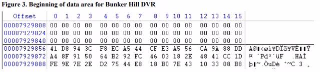
Figure 3. Beginning of data area for Bunker Hill DVR
Figure 4. Beginning of data area for Swann DVR
Figure 5. Video data with beginning of parameter sets and I-frame highlighted from zero byte (Bunker Hill DVR)
Figure 6. Video data with beginning of parameter sets and I-frame highlighted from zero byte (Swann DVR)
Figure 7. NAL units decoded from table above (Bunker Hill DVR)
Figure 8. NAL units decoded from table above (Swann DVR)
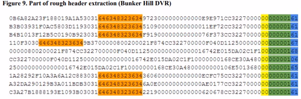
Figure 9. Part of rough header extraction (Bunker Hill DVR)
Figure 10. Part of rough header extraction (Swann DVR)
Figure 11. Demultiplexing chunk-level multiplexed data
Figure 12. Demultiplexing block-level multiplexed data
Note: Images in figures 1, 2, 3, 6, 7, 10, 11, 12 and Appendix B belong to the Forensic Audio Video Evidence Unit, Victoria Police Forensic Services Department. [1]
1. Purpose
The purpose of this document is to present advanced techniques for data recovery from security system digital video recorders (DVRs) when the data cannot be recovered using the guidelines provided in SWGIT Section 24 Best Practices for the Retrieval of Digital Video [2].
2. Scope
This document provides advanced recovery methods specific to security system DVRs storing video streams in the H.264 format. It is not intended for non-security DVRs such as those used for broadcast/cable television, gaming devices, and personal video recorders, nor has it been used to recover other video formats. Additionally, these methods should not be used by personnel not trained in the methods and techniques to which they refer. Traditional methods of recovery, such as those described in [2] or in traditional computer forensic capabilities should be attempted first. These advanced techniques should only be attempted after all other options have been exhausted.
3. Limitations
The documented technique has been shown to be successful in recovering video segments of data stored in the H.264 format only. Other video formats have not been tested.
The recovered data may require additional processing to portray the original recording properly, such as aspect ratio adjustments, frame rate adjustments, sequencing, and de-multiplexing.
Additional or alternate methods may be required to recover audio information and/or metadata. All video stored on the DVR may not be recovered through these methods.
4. Requirements
4.1 Case specific items
- Original DVR (if possible), or same make/model DVR, with power supply
- Forensic clone(s) and/or image(s) of the evidence hard drive(s)
- If data to be recovered is incident specific, request date/time of event and any known visual cues
4.2 Equipment
- Hardware write blocker
- Hex editor software (capable of viewing, editing, searching, carving, and concatenating)
- Video playback software (capable of decoding multiple video formats)
- (Optional) Software capable of extracting header data and/or assisting in demultiplexing
4.3 Technician/Examiner Qualifications
Personnel performing these advanced recovery techniques should meet technician/examiner level of training and experience as defined in the SWGDE/SWGIT Guidelines & Recommendations for Training in Digital & Multimedia Evidence [3]. This should include experience in the use of a software hex editor and command line operations.
5. Recovery Methods
The flowchart in Appendix A provides an overview of the decision making process to follow in order to determine the best data recovery process a technician should utilize. The most difficult level of recovery, video frame recovery, is defined below.
5.1 Video Recovery, Targeted by Time and Date of Incident
The procedure described here is recommended when the requested examination is to recover footage from an incident at a specific time and date. In each case, the examiner will begin by attaching the previously prepared forensic clone to a write blocker, and loading the data contained on the clone into the chosen hex editing software.
5.2 Identify H.264 data
As stated in the limitations, this method is best suited for H.264 data. With slight modifications, this method may be applied to other video formats, but this is beyond the scope of this document.
H.264 data typically consists of a byte stream encasing a Network Abstraction Layer unit (NAL unit). The compressed data is contained within these NAL units. The first byte of a NAL unit is used to identify the kind of data contained inside.
Each NAL unit is preceded in the byte stream by a zero byte followed by a start code prefix. A zero byte is simply the byte 0x00 and a start code prefix is a sequence of three bytes, 0x000001. Therefore, each NAL unit should begin with the five byte sequence 0x00000001ab, where ab denotes a valid first byte for a NAL unit.
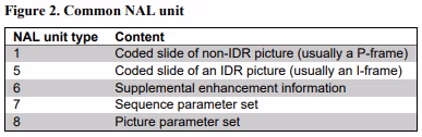
To read the first byte of a NAL unit consists of three parts, described in Section 7.3.1 of [4]. The first bit is called the forbidden zero bit and is always 0 for valid H.264 NAL units. The following two bits are the NAL ref idc. These bits can take any value (depending on the NAL unit type) so are of little diagnostic value. Higher values tend to indicate that the NAL unit is of higher importance. The final five bits contain the NAL unit type. The NAL unit type can take many values as detailed in Table 7-1 of [4], but the most likely values are summarized in the table below.

A simple way to quickly assess whether a NAL unit is valid and determine its contents which works for the majority of NAL units encountered in security DVR footage is to consider the two octets separately. Therefore, if the first byte is written 0xab, then the first octet is a and the second is b. If the octet a is greater than seven, then it is not an H.264 NAL unit (as the forbidden zero bit is not zero). In most cases, the octet a will be an even value: 2, 4, 6 or less commonly, 0. If this is the case, then the octet b is equal to the NAL unit type and the contents for most NAL units can be determined by referring to the table below.
If the video data is of type H.264, it should contain numerous valid NAL units. This can be determined using a hex editor. This is done by locating the video data, searching it for occurrences of 0x00000001 and then checking the following byte to ensure that it is a valid NAL unit.
5.2.1 Locating the start of the video data
The video data should be compressed. Compressed data should be identifiable as predominantly having high entropy / low redundancy (that is, the data is unpredictable) as evident in the following example taken from a Swann brand security digital video recorder. Note that the NAL units may not be evident at the beginning of the video data, but may begin further into the drive.

5.2.2 Locate an I-frame and parameter sets
H.264 data found in security DVR footage typically consists of I-frames (intra-frame encoded frames) and P-frames (predictive encoded frames). B-frames would be unusual for a system which is recording “on the fly” as they would require the system to look ahead. I-frames are the most useful for diagnostic purposes, as they do not depend on any other frames.
Each I-frame is usually encoded in a single NAL unit of type 5. In order to decode frames, both sequence and picture parameter sets are required (types 7 and 8). These are usually small NAL units located just prior to an I-frame. If a section of byte stream data is extracted from the first parameter set prior to an I-frame through to the end of the I-frame then tools like ffmpeg should be able to interpret and play or transcode this data. Again, this can be located by searching through the video data for the bytes 0x00000001 until the following byte indicates a NAL unit containing an IDR picture or a parameter set (see Figure 5 and Figure 6 below).
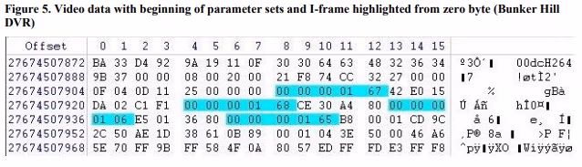

Figure 7. NAL units decoded from table above (Bunker Hill DVR)
| Offset | Bytes | NAL ref idc | NAL unit type | Content |
|---|---|---|---|---|
|
27674507912 |
Hex 0000000167 |
6 |
7 |
Sequence parameter set |
|
27674507924 |
Hex 0000000168 |
6 |
8 |
Picture parameter set |
|
27674507933 |
Hex 0000000106 |
0 |
6 |
Supplemental enhancement information |
|
27674507942 |
Hex 0000000165 |
6 |
5 |
Coded slice of an IDR picture (usually an I-frame) |
Figure 8. NAL un its decoded from table abov e (Swann DVR)
| Offset | Bytes | NAL ref idc | NAL unit type | Content |
|---|---|---|---|---|
|
0x020855DCB0 |
0x0000000127 |
2 |
7 |
Sequence parameter set |
|
0x020855DCD4 |
0x0000000128 |
2 |
8 |
Picture parameter set |
|
0x020855DCDD |
0x0000000106 |
0 |
6 |
Supplemental enhancement information |
|
0x020855DCF6 |
0x0000000125 |
2 |
5 |
Coded slice of an IDR picture (usually an I-frame) |
5.2.3 Extract a sample
Beginning with the first zero byte of the first parameter set, select and copy a section of footage as a sample. A selection of 30MiB should be a reasonable practical size. In the example above, this would be a continuous section of 30MiB beginning at offset 0x020855DCB0.
Once the sample has been saved, the data can be encapsulated in an Audio Video Interleave (AVI) container using ffmpeg with the following options:
ffmpeg –f h264 –i input_file –c:v copy output_file.avi
If this fails, it is possible that transcoding the data are encapsulating the data into a different container may help. This can be done by substituting –c:v huffyuv for –c:v copy or by changing the output file extension from .avi to .mkv respectively.
If this still fails, it may be due to blocking or the wrap-around point may have been selected (not covered here). Another sample should be taken using the same method but from another location in the disk and the process repeated. This can be repeated a few times at various points, however if multiple sections fail it is likely that techniques beyond the scope of this document are required for recovery if at all possible.
5.3 Decoding headers
Many security DVR systems include header data at the beginning of each chunk of video. If the video is encoded as H.264, each chunk will typically include a header followed by a section of H.264 byte stream data and sometimes a footer. The byte stream in turn usually consists of either multiple NAL units (at least a picture parameter set, a sequence parameter set and an IDR slice) if the chunk contains an I-frame or a single NAL unit (a non-IDR slice) if the chunk contains a P-frame.
Each NAL unit is preceded by the four bytes 0x00000001 (a zero byte followed by a start code prefix). The first byte of a NAL unit can be used to determine the type of data contained within according to Section 7.3.1 and Table 7-1 of [4].
The header data often includes the camera number, date and time. It is usually possible to decode the needed parts of the headers and retrieve this data which can then be used to recover specific portions of video based on camera, date, and time. One method is given below.
Extracting headers can be done with a hex editor, but the process is laborious and lengthy for a large number of headers. It is best to use a computer program if one is available, or write one if it is not.
5.3.1 Sample footage
In many cases where recovery is required, the security DVR system is not available or cannot be used. If the system is available, or a very similar system is available, then it is best to create some test footage first. A small hard drive should be used, wiped with a known byte pattern such as 0x00 or 0xFF. A short amount of footage can then be recorded using multiple inputs. This way when decoding the headers, the true values of the parameters such as date, time, and the number of cameras are already known.
If this is not possible, the evidence can be used, but parameters such as the date and time should be verified by other means if possible or assumptions may need to be made.
5.3.2 Rough header extraction
Find each occurrence of 0x00000001 within the video data. For each occurrence, extract n bytes beginning before the 0x00000001 and ending with the last byte following the 0x00000001 (which should be the first byte of the NAL unit, including the NAL unit type). In this case n is the estimated length of the header plus five bytes. It does not matter if this is over-estimated at this stage; 128 bytes should be more than sufficient.
5.3.3 Locate signature and refine headers
The rough extraction will likely result in false positives. Each chunk containing an I-Frame will typically contain multiple occurrences of the bytes 0x00000001, but only the first will be relevant. Correctly identified headers will likely have a significant degree of similarity between bytes in the same locations. This rough alignment can be used to locate a signature, a set of bytes which are unlikely to occur by chance but occur unchanged in each correctly identified header within the video data.
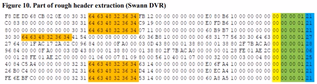
The example below consists of the last 37 bytes of ten consecutive “rough headers” extracted in the manner described above from a Swann brand security digital video recorder system. The zero bytes have been colored yellow, the start code prefixes colored green, and the first byte of the NAL units have been colored blue. The bytes 0x646348323634 (equivalent to the text “dcH264”) can be seen whenever the NAL unit is of type 1 or type 7, corresponding to chunks containing P-frames and chunks containing I-frames respectively. It cannot be seen from this small extract, but the type 8, type 6 and type 5 NAL units are all contained in the same I-frame chunk which is why they do not have (or need) a signature. Note that the headers for I-frames differ slightly to the headers for P-frames.
5.3.4 Refine list of headers using the signature
Step one is repeated, but using the signature bytes in place of the 0x00000001. This step as well as following steps can be seen in Appendix B – Table of extracted headers from Swann DVR.
5.3.5 Assess the header list
The new header list should consist of every valid header but no invalid headers. If this is not the case, another signature should be selected (return to step 3). If a signature cannot be found that singles out correct headers then it is better to include false positives than exclude correct headers, or a more complex method can be used using conditional logic. Note that blocking can cause headers to be divided and possibly excluded. This is addressed later (see 5.4.2).
If headers are being extracted by hand, it is not feasible to extract a great many. In this case, it is best to try and extract one or two corresponding to each different NAL unit that contains a header (usually just types 1 and 5).
5.3.6 Locate the camera, date/time, length and frame type in the header
The camera, date/time, frame type and the length of the chunk are usually stored in the header. A process of “reverse engineering” can be used to determine how these are stored. By lining up the headers, these parameters become much more obvious.
Camera. The camera will usually be stored as a number. The number is likely to be limited to a few values, usually low (such as the numbers 0 to 7 for an 8 camera system). The camera number will typically be repeated before changing with multiple consecutive chunks coming from the same camera.
Date/Time. The date and time is usually stored as a single set of four or more bytes. This often resembles ISO 8601 format or Unix/Epoch format, though usually stored relative to the local time and not UTC. The date/time will predominantly be monotonically increasing for each single camera and may decrease when the camera number changes. The number may repeat before increasing depending on frame rates. Sometimes it is only recorded for some chunks (such as chunks containing I-frames).
Length. The length of byte stream data contained in the chunk can be estimated manually using a hex editor. The byte stream begins with the zero byte and continues until approximately the next header. In some cases, there may be some padding bytes. The manually obtained number can be compared with numbers found in the header until the length is found. Alternatively, the length can simply be calculated for each chunk using the above method.
Frame type. As described above, chunks typically contain I-frames or P-frames, and usually only a single frame contained in a single slice. This frame type can be read from the NAL unit type; chunks containing I-frames typically begin with a sequence parameter set or picture parameter set (type 7 or 8) while P-frames typically have only one NAL unit, a non-IDR slice (unit type 1). Often the header will also contain the frame type as well. While it is not always essential to decode the frame type, sometimes the header format will depend on it and so knowing the frame type can help in decoding the other parameters.
Endianness. Often numbers are stored as little-endian integers, meaning that the least significant byte comes first so that the bytes 0x01020304 should be read as the hexadecimal number 0x04030201.
Example. Referring to the example of the Swann system represented in Appendix B – Table of extracted headers from Swann DVR, the headers have been aligned on their signatures and the various parameters have been colored.
The first column corresponds to the camera number where 0x30 (ASCII ‘0’) represents camera 1 and 0x32 (ASCII ‘2’) represents camera 3. The second (pink) column holds the frame type. In this case, 0x30 (ASCII ‘0’) represents a chunk containing an I-frame and 0x31 (ASCII ‘1’) represents a chunk containing a P-frame. These first two columns combined with the next two (always “dc”) may look familiar when considering the AVI standard. Though they bear a resemblance, they are not quite consistent.
Columns 0x02 to 0x07 (in orange) contain the signature used to identify and align the headers. In this case, the signature was the string “dcH264”. The signature often remains consistent between different systems from the same manufacturer but can vary between manufacturers. The signature is immediately followed by two columns holding the length of the byte stream data contained in the chunk (colored blue) as a little-endian integer.
The time code is stored in columns 0x18 to 0x1B, but only in chunks containing I-frames. The timecode is stored in a manner similar to Unix-time as a little-endian integer. This can be decoded using on-line decoders, hex editors, in spreadsheets or using computer programs. The byte stream containing the video data within the chunk begins at column 0x18 or column 0x20 depending on whether the frame type contained in the chunk is a P-frame or I-frame respectively.
5.4 Demultiplexing and extracting footage
Security DVRs often multiplex data so that multiple cameras may be stored on the same disk. This causes the video in extracted samples to switch rapidly between multiple camera views. If switching occurs part-way through a GOP, this will cause errors to occur in the footage. With blocking, the footage may even switch part way through a chunk. The rapid changing of camera and errors in decoding may make the video difficult or impossible to view or decode.
However, using the information decoded from the extracted headers it is possible to demultiplex the video at the data level. The optimum method to use depends on how the data has been multiplexed. The two most common methods are chunk-level multiplexing and block-level multiplexing.
Demultiplexing is laborious and is again best done using a computer program. Small sections of footage can be demultiplexed by hand, particularly deblocking. However, it is not practical to do this for large sections of footage, particularly if it is multiplexed at the chunk level. For this reason, the next sections are written with the assumption that a computer program is used to perform the task.
If a computer program is not available and a hex editor must be used, then it is best to locate the required headers within the video data rather than attempt to extract any useful number of headers to begin with. If the desired parameters are known and the header format has been at least partially reverse engineered, then it is possible to create at least part of a desired header using the desired parameters. The hex editor can then be used to search the video data for this header.
For example, from the Swann system decoded above, any header created on Sunday the 20th of December, 2015 at 22:53:33 corresponding to an I-frame captured from camera one should contain the bytes 0x000000006D317756303064630000000127. Searching the video data for these bytes should find the relevant section. This is a very long string of bytes and very unlikely to result in a false hit.
5.4.1 Demultiplexing chunk-level multiplexed data
Chunk-level multiplexing involves interleaving the chunks in a similar manner to that found in containers formats like the AVI format.
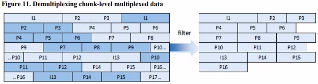
Demultiplexing chunk-level multiplexed footage is simpler than for block-level multiplexed data and works quite well on both forms of multiplexing, so it is recommended that if the form of multiplexing is unknown that this method is tried first.
To extract a single camera, iterate through each header and perform the following steps:
- If the header is not from the selected camera, continue on to the next header.
- If the header is not from the required date and time period, continue on to the next header.
- Beginning with the first zero byte in the chunk, append all of the byte-stream data to the output file (that is, the contents of the chunk excluding the header and any footer or padding bytes).
Once all headers have been filtered and all data extracted in this way, the output file should contain an H.264 byte stream. There is no guarantee that the first frame is an I-frame, so the beginning of the file should be trimmed first. This can be done by locating the first I-frame as done when extracting a sample and removing all data before it. Alternatively, this can be incorporated into the above algorithm.
If the footage was multiplexed at the block level (blocking) then there may be incomplete chunks remaining within the footage. It is likely that these will still cause errors, though they will likely be few, particularly when compared to the original sample taken. Again, whether or not further work needs to be done is dependent upon the case.
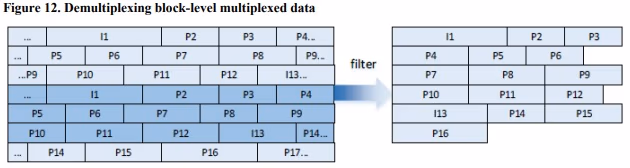
5.4.2 Demultiplexing block-level multiplexed data
Data may be multiplexed at the block level. The stream of data from each camera is converted into chunks as normal. These chunks are then concatenated into a separate stream for each camera. These streams are then divided into blocks of equal size and interleaved with each other.
To demultiplex blocked data, the video data must be divided into blocks. To do this the start of the first block must be known and the block size must be either known or estimated. The start of the first block is usually at the start of the video data and the block size can be estimated with the help of the list of headers.
Each block contains footage from only a single camera. In addition, block lengths tend to be “nice” numbers, such as 0x10000 or 0x20000 bytes (the Swann system used in the example is blocked with a block size of 0x20000 bytes). The block boundaries can be estimated by looking at the offsets of the last header of one camera and the first header of another; the boundary must lie between the two. By observing a number of these camera transitions, an estimate can be made as to the block size.
Once the data has been separated into blocks it can be deblocked for a single camera using the following steps.
For each block:
- Get all of the headers in that block
- Check that all headers have the same camera number. If not, the block parameters are wrong; terminate the algorithm.
- If the camera is not the selected camera, continue to the next block.
- If none of the headers contain a date and time of interest, continue to the next block.
- Copy the entire block (do not extract the byte streams at this stage) into the output file.
It may be possible to play or transcode the deblocked data using ffmpeg without extracting the byte stream first. The file still requires trimming as with chunk-level demultiplexing, as again there is no guarantee that the footage begins with an I-frame and parameter set.
If the footage cannot be transcoded or played, or there are significant errors, the byte stream may have to be extracted. Headers should be extracted from the deblocked file. This should be done as any header that was divided across a block boundary will likely contain incorrect parameters, and some headers may have been missed altogether if the signature bytes were divided across different blocks.
Once the headers are extracted, the byte stream can then be extracted from the deblocked file just as with demultiplexing the chunk-level multiplexed data, though there is no need to check the camera number in this case. The resulting file will be raw H.264 data just as with the chunk-level demultiplexing, though again it may need to be trimmed.
Note that sometimes the data may be divided into multiple partitions. This can cause the demultiplexing to fail if one partition is offset by a fraction of a block from another. The easiest solution is to demultiplex partitions separately. Often the extracted headers can be used to find the required partitions. If only a small amount of footage is needed, in most cases it will be found on a single partition. Identifying partition boundaries is out of the scope for this document, though it is often not difficult and only requires a hex editor.
6. Additional Guidance
Refer to SWGIT Best Practices for the Analysis of Digital Video Recorders [5] for guidance on equipment preparation, acquisition, analysis, documentation, and reporting.
7. References
The following documents are referenced in this document:
[1] “Original images,” Forensic Audio Video Evidence Unit, Victoria (Australia) Police Forensic Services Department, 2016.
[2] Scientific Working Group on Imaging Technology. Section 24: Best Practices for the Retrieval of Digital Video. [Online]. https://www.swgit.org/documents/Current%20Documents
[3] Scientific Working Group on Digital Evidence and Scientific Working Group on Imaging Technology. SWGDE/SWGIT Guidelines & Recommendations for Training in Digital & Multimedia Evidence. [Online]. https://www.swgde.org/documents/Current%20Documents
[4] Telecommunication Standardization Sector of ITU, “H.264 : Advanced video coding for generic audiovisual services,” Standard No. H.264, 2013.
[5] Scientific Working Group on Imaging Technology, “Section 23: Best Practices for the Analysis of Digital Video Recorders”. [Online]. https://www.swgit.org/documents/Current%20Documents
Appendix A – Decision-Making Process for DVR Recovery Methods

Appendix B – Table of extracted headers from Swann DVR

History
| Revision | Issue Date | Section | History |
|---|---|---|---|
|
1.0 |
01/15/2015 |
All |
Original release; titled SWGDE Best Practices for the Recovery of Data from CCTV Digital Video Recorders. Voted by SWGDE for release as a Draft for Public Comment. |
|
1.0 |
02/05/2015 |
All |
Formatting and technical edit performed for release as a Draft for Public Comment. |
|
— |
06/04/2015 |
All |
Committee voted to remove the draft from public comment for rewriting. |
|
1.1 |
09/16/2015 |
Title, All, Appendix A |
Committee retitled the document, SWGDE Proposed Techniques for Advanced Data Recovery from Security Digital Video Recorders, restructured and rewrote all sections, and added a decision process flow chart as an appendix. Voted by SWGDE to re-release as a new Draft for Public Comment. |
|
1.1 |
9/29/2015 |
All |
Formatting and technical edit performed for release as a Draft for Public Comment. |
|
1.2 |
01/14/2016 |
All, Appendix B |
Significant content changes were made throughout and Appendix B was added in response to public comments. Voted by SWGDE to re-release as a new Draft for Public Comment. |
|
1.2 |
02/08/2016 |
All |
Formatting and technical edit performed for release as a Draft for Public Comment. |
|
1.2 |
06/09/2016 |
— |
SWGDE voted to publish as an Approved document. |
|
1.2 |
06/23/2016 |
— |
Formatted and posted as an Approved document. |
Version: 1.2 (June 23, 2016)